

Fig. 4
Fig. 5a
E-Bus from the cen-
tral control unit
E-Bus to other
accessories
Fig. 5b
WAC 12
WAC/WAS 11
Audio to
other
WAC 12
Fig. 5c
e.g. WMA 11
WAC 12
WAS 11
Fig. 5d
WAC 12
WAC 11
WAC 11
The right to make technical changes to the described equipment without prior notice is
reserved.
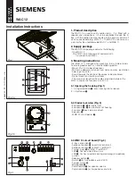
3.4 Mounting (Fig. 4)
- The housing can be mounted flat or at 45
o
.
- Always use two attaching points which are one above the
other, including for corner mounting.
4. Wiring
4.1 E-Bus (Fig. 5a)
The use of type 24 AWG 7x0,2 mm dia. cable is recommended.
The E-Bus cable shall not be more than 500 m long. The WAC 12
must be connected to the central control unit via the E-Bus (B1-,
B2, B3, B4+). It can be routed parallel to other accessories.
4.2 Tamper (Fig. 5a)
The tamper inputs T- and T+ must be short-circuited if not wired
to a WAC 11 or WAS 11.
4.3 Audio (Fig. 5b)
To avoid side-tone, a twisted core pair at least 0.6 mm in dia.
must be used. The audio connection to the central control unit
must not be more than 200 m long. The audio output depends
on the cable length and core cross-section. The audio connection
(A- and A+) of the WAC 12 must be connected to the audio input
(A- and A+) of the central control unit (e.g. WMA 11).
4.3.1. WAC 11 and WAS 11 (Fig. 5c)
The audio outputs (A- and A+) of the WAC 11 and WAS 11 are
connected to the audio inputs (AE- and AE+) of the WAC 12. The
tamper outputs (T,T) of the WAC 11 and WAS 11 are connected
in series to the tamper inputs (T- and T+) of the WAC 12.
Where several WAC 11 are used, all WAC 11 must be connected
directly to the WAC 12 to obtain optimum per for man ce (Fig. 5d).
5. Start-up
5.1 Microphone sensitivity
The sensitivity of the microphone must be matched to the room
and ambient noises (potentiometer
U
, Fig. 3).
Where sensitivity is reduced, the reception of quiet signals
naturally reduces. The following ranges are normally obtained.
- Approx. 3.5 m with potentiometer on min.
- Approx. 6.5 m with potentiometer on mid position.
- Approx. 8.5 m with potentiometer on max.
5.2 Speaker
Set the required volume using potentiometer (
Y
, Fig. 3).
5.3 LED „microphone active“
- Switch (
E
, Fig. 3) open: LED active.
- Switch (
E
, Fig. 3) closed: LED inactive.
6. Close housing
1 - Engage cover at the top in the openings in the base of the
housing.
2 - Close the cover by pushing downwards until the locking
tab engages.
7. Technical data
Supply Through
E-Bus
Power consumption, quiescent state
5 mA
Power consumption, "challenge" state
24 mA
Operating temperature
-10°C to +55°C
Housing material
ABS
Dimension in mm
H 145 x B 105 x T 70
Safety class
IP 30
Weight 230g
T+
T-
B2 B3 B4+
B1-
A+
A-
A+
A-
T+
T-
AE+
AE-
T
T
A- A+
NC
T
T
A- A+
A+
A+
A-
A-
AE+
AE-


