Installation
4.9 Installing and removing the shaft-mounted gearbox
BA 2012
28
Operating Instructions, 03/2013, 70000004024300
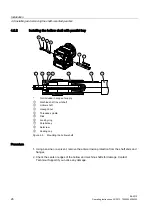
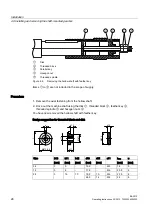
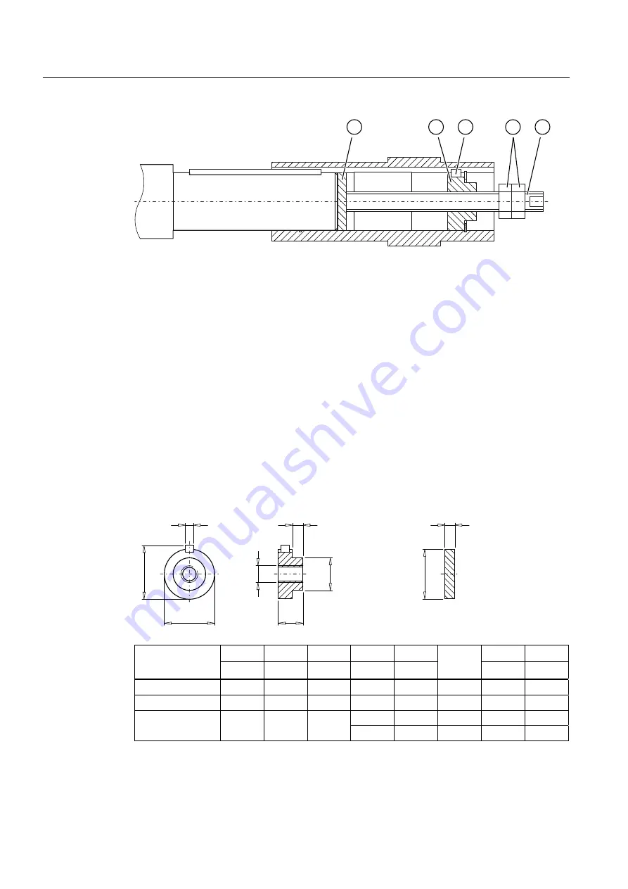
①
Disk
②
Threaded block
③
Parallel key
④
Hexagon nut
⑤
Threaded spindle
Figure 4-6
Removing the hollow shaft with feather key
Items
①
to
⑤
are not included in the scope of supply.
Procedure
1.
Remove the axial fastening from the hollow shaft.
2.
Drive out the machine shaft using the disk
①
, threaded block
②
, feather key
③
,
threaded spindle
⑤
and hexagon nuts
④
.
You have now removed the hollow shaft with feather key.
Design suggestion for threaded block and disk
G
V
G
E
G
E
E
X
W
b10
b11
b12
d10
d11
t
max
u
Size
[mm]
[mm]
[mm]
[mm]
[mm]
s11
[mm]
[mm]
08
3
5
-
15.9
-
M5
18
5
18
3
6
-
17.9
-
M6
20.5
6
19.9
10
M6
22.5
6
28
3
15
10
24.9
14
M8
28
8
Summary of Contents for Worm Gearbox S 5 BA 2012
Page 1: ...Answers for industry MOTOX MOTOX Worm Gearbox S BA 2012 Operating Instructions 03 2013 ...
Page 2: ......
Page 34: ...Commissioning BA 2012 32 Operating Instructions 03 2013 70000004024300 ...
Page 36: ...Operation BA 2012 34 Operating Instructions 03 2013 70000004024300 ...
Page 44: ...Disposal BA 2012 42 Operating Instructions 03 2013 70000004024300 ...
Page 53: ......


