MapIT G2 Hardware Installation Training Manual
Confidential – June 2014
14
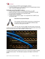
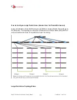
When a MapIT G2 Patch Cable is inserted or removed from a port, the Smart Panel
discovers the connection and communicates the port ID information to the MCP via the
Control Bus cable. The MCP relays the information to the EEC software over a TCP/IP
connection. Any changes in connectivity are immediately updated in the EEC
database. This provides network administrators with vital up-to-the minute information
about the status of their network, from the hardware layer and up… anytime,
anywhere.
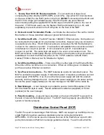
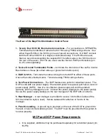
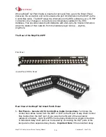
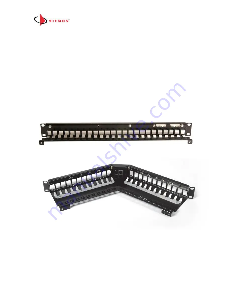
The Rear of the MapIT G2 SPP
Flat Panel
Angled Panel/TERA Panel
Rear View of the MapIT G2 Smart Patch Panel
1. Flat Panels
– have two S110 Control Bus Cable Connections.
Terminate the
control bus cables routed from the MCP or DCP to the IN port. Daisy chain Control
Bus Cables from the OUT port of one panel to the IN port of the next panel
(adjacent or below). Up to five SPPs can be daisy chained on a single connection.
A redundant daisy chain path can be created by connecting the OUT ports of the
last panels of two separate daisy chains.
Important
Note
: If the redundant daisy


