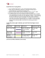
MapIT G2 Hardware Installation Training Manual
Confidential – June 2014
15
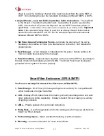
chain is used, the two Daisy chained links must be served from the same MCP or
DCP. Do not attempt to span the redundant link between different MCPs or DCPs.
2.
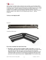
Angled Panels
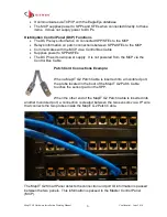
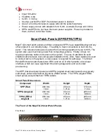
– have two RJ45 Control Bus Cable Connections
. The top RJ45
is the IN port. The bottom is the OUT port. Connect the IN port to a port on the
MCP, connect the OUT port to the IN port of the next SPP in the daisy chain (if
applicable).
A maximum of five panels can be connected in each daisy chain.
Important
Note
: If the redundant daisy chain is used, the two Daisy chained links must be
served from the same MCP or DCP. Do not attempt to span the redundant link
between different MCPs or DCPs.
3. Flat Panel Ground Termination Points
–
terminate the drain wire of the cat 5e
bus/daisy chain cables on these (one drain wire per connector). Not required for
angled panels
4. Rear Manager
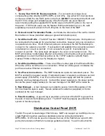
– A rear manager is integrated into the panel. Secure cables with
Velcro or cable ties securely to the manager.
4. Panel Grounding
– A ground lug is provided on the rear of the SPP for grounding to
the rack or telecommunications ground (TGBB). The Smart Panel must be properly
grounded for the system to function properly
Smart Fiber Enclosures (SFE & SMTP)
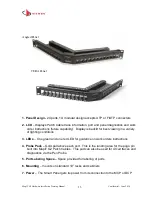
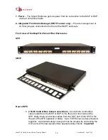
The Front of the MapIT G2 Smart Fiber Enclosure (SFE & SMTP)
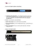
1. Panel Design
–
48 LC fiber (24 managed duplex connections) 1U, compatible with
either multimode or single mode fiber
2. LCD
– Displays Patch Cable trace information, port and panel diagnostics and work
order instructions (future capability). Display is backlit for best viewing in a variety
of lighting conditions
3. LEDs
– Provide guidance for work order instructions
4. Probe Pads
–
Used for diagnostics and is the landing area for the pogo pin built into
MapIT G2 Fiber Jumpers
5. Port Labeling Space
–
Space provided for labeling of ports and panel
6. Mounting
– mounts on standard 19” racks and cabinets


