MapIT G2 Hardware Installation Training Manual
Confidential – June 2014
16
7. Power
– The Smart Enclosure gets its power from its connection to the MCP or DCP
via the Control Bus Cable
8. Integrated Front Cable Manager (SMTP version only
)
– Provide management of
LC fiber jumpers connected to the front of the SMPT enclosure
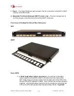
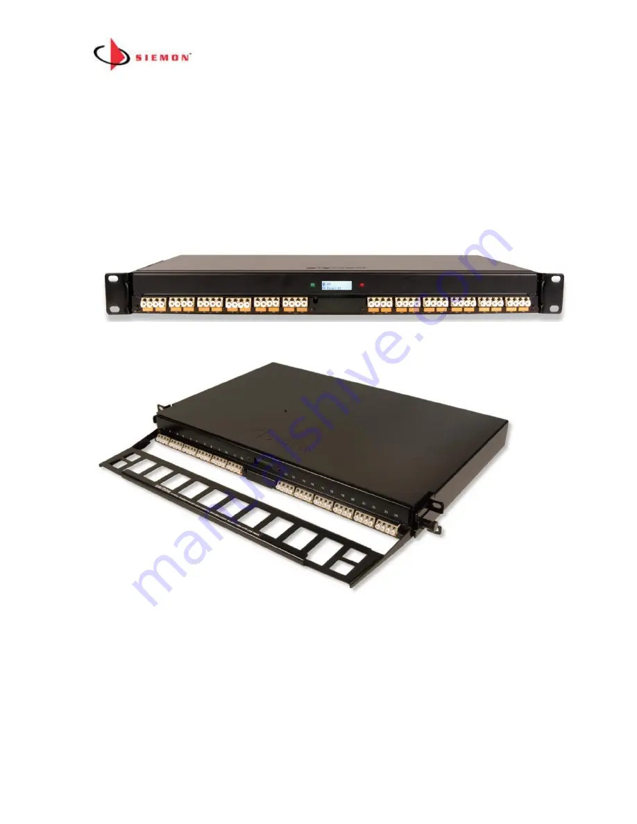
Front view of the MapIT G2 Smart Fiber Enclosures
SFE
SMTP
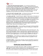
Rear of SFE
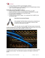
1. 2 RJ45 Control Bus Cable Connections
–Connect the Control Bus
cable routed from the MCP or DCP to the IN port on the inside of the
SFE. Daisy chain control bus cables from the OUT port of the SFE to the
IN port of the SFE adjacent or below. Up to 5 SFEs can be daisy chained
together. A redundant daisy chain path can be created by connecting the
OUT ports of the last panels of two separate daisy chains.
Important

