MapIT G2 Hardware Installation Training Manual
Confidential – June 2014
5
▪
Automatic updates when work orders are completed
▪
Track costs for work orders by department
▪
Email/text alerts on email status
▪
SNMP traps alert 3
rd
party software of work order status
▪
Auto routing feature helps design the best path for new circuits or location in a
rack
▪
Greater efficiency reduces the cost of moves, adds and changes
Enhanced Security
▪
Detects when unauthorized devices connect to the network
▪
Monitors network for unauthorized activity such as patching changes, device
movement or device disconnection
▪
Wide variety of responses to unauthorized activity include email and text alerts,
snmp commands to disable switch ports, IP camera pictures
▪
Maintains an audit log of all network events
▪
EagleEye database can be backed up remotely and used for disaster recovery
How the MapIT G2 System Works
Smart Patch Panels (SPP) and Smart Fiber Enclosures (SFE) have the built in ability to
track patch connections. This connection information is transmitted to the Master
Control Panel (MCP) supporting the patch zone. The MCP relays this patch
connection information via TCP/IP
over the customer’s LAN/WAN to the EagleEye
database. It is also possible to expand the capability of a given patching zone by
installing Distribution Control Panels (DCP) to support large numbers of SPPs and/or
SFEs.
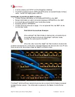
Panel to Panel Communication
•
Each port on a SPP or SFE has unique port ID. When two ports are connected
with a MapIT G2 Patch Cable or Fiber Jumper, the panels will sense the ID of
the connected ports and transmit that information back to the MCP/DCP
•
The initial setup of the system will detect all ports within 2 minutes or less
•
Subsequent changes are detected within 3 seconds
•
Each SPP/SFE is connected to the MCP or DCP via a Control Bus Cable
Master Control Panel (MCP) Functions
•
The MCP tracks new items that are connected in the Patch Zone (DCPs, SPPs
and SFEs)
•
The MCP collects connection data from the panels in the Patch Zone


