MapIT G2 Hardware Installation Training Manual
Confidential – June 2014
9
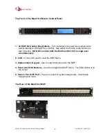
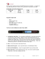
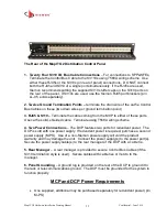
1. Twenty Four S310 I/O Bus Connections
– For connections to lower level
components (either directly to SPPs/SFPs or to DCPs). Use either S310 connections
on the rear of MCP or the RJ45 ports on the front.
DO NOT
connect both the RJ45 and
the S310 of a single port simultaneously. If the RJ45 ports are used, Siemon
recommends putting the supplied S310 stuffer caps on the S310 ports on the rear of
the panel. If S310s are used, use the Siemon RJ45 port blockers (p/n LL-05, sold
separately) to prevent access to the RJ45 ports on the front of the MCP.
2. Twelve Ground Termination Points
–
terminate the drain wire of the cat 5e Control
Bus Cables on these (two drain wires per ground termination point)
3. Two Ethernet RJ45s
– The MCP has two 10BASE-T Ethernet ports. Both ports can
be connected to the network for a redundant connection, however only one connection
is operational at a time. If both Ethernet ports are connected, the MCP will attempt to
connect to the network on port #1. If successful it will establish the connection and will
not attempt to connect on port #2. If not successful on port #1, it will attempt to
connect on port #2. The same logic will apply in the event a connection is lost. The
MCP will continue to alternately attempt connections on both ports until a connection is
established. Connect the Ethernet port(s) to the TCP/IP network via RJ45 Patch
Cables (T568A or B wired, Cat 5e Shielded or higher).
4. Two Ethernet Status LEDs
– There are LEDs on either side of the Ethernet RJ45s.
When the LED is not lit there is no connection. When an LED is green it indicates the
port has an active Ethernet connection
5. Two Power Connections
– The MCP features two ports for redundant power. The
MCP is sold with one power supply. If redundant power is required, purchase a second
power supply (P/N M-PS). Use of a non-Siemon power supply will void the product
warranty and may damage the unit. Connect the power supply(s) to the power port(s).
Secure the power supply cable(s) to the rear manager of the MCP with a cable tie.
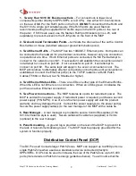
6. Rear Manager
– A rear manager is provided to secure Control Bus cables (if the
S310 termination style is used). Secure cables with cable ties (supplied) or Velcro
(optional) to the rear manager.
8. Panel Grounding
– A ground lug is provided on the rear of the MCP to ground it to
the rack or telecommunications ground. The MCP must be properly grounded for the
system to function properly.
Distribution Control Panel (DCP)
The DCP is used to create larger Patch Zones. MCP can support up to 2880 ports in a
single Patch Zone when used as a standalone device connected directly to
SPPs/SFEs. DCPs can be used to increase the size of the Patch Zone up to 65,000
ports (more details on Patch Zone design guidelines below). You will notice that the


