background image

Table of Contents

2

Safety Information  . . . . . . . . . . . . . . . . . . . . . . . . . . . . . . . . . . . . .3

Cabinet Mounting  . . . . . . . . . . . . . . . . . . . . . . . . . . . . . . . . . . . . .4

Cabinet Reversal  . . . . . . . . . . . . . . . . . . . . . . . . . . . . . . . . . . . . . .5

Mounting Rail Adjustment  . . . . . . . . . . . . . . . . . . . . . . . . . . . . . . . .6

Optional Cable Management Finger Installation  . . . . . . . . . . . . . . . .6

Cable Manager Installation . . . . . . . . . . . . . . . . . . . . . . . . . . . . . . .7

Cabinet Bonding  . . . . . . . . . . . . . . . . . . . . . . . . . . . . . . . . . . . . . .8

!

i

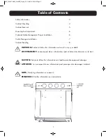
WARNING:

Failure to follow this information can result in injury or death.

AVERTISSEMENT:

Le non-respect de ces informations peut entraîner des blessures ou la mort.

CAUTION:

Failure to follow this information can lead to possible equipment damage.

ATTENTION 

Le non-respect de ces informations peut provoquer des dommages matériels.

NOTE:

Clarifying information or comment.

REMARQUE:

Clarifier information ou commentaire.

INS_100.22796.00_WallMT_B.qxp_A  2/18/20  8:34 AM  Page 2

Summary of Contents for WC2 101-12U Series

Page 1: ...Wall Mount Cabinet Instructions www siemon com INS_100 22796 00_WallMT_B qxp_A 2 18 20 8 34 AM Page 1 ...

Page 2: ... information can result in injury or death AVERTISSEMENT Le non respect de ces informations peut entraîner des blessures ou la mort CAUTION Failure to follow this information can lead to possible equipment damage ATTENTION Le non respect de ces informations peut provoquer des dommages matériels NOTE Clarifying information or comment REMARQUE Clarifier information ou commentaire INS_100 22796 00_Wa...

Page 3: ...of equipment should be connected to a dedicated branch circuit Enclosure must be wired per applicable sections of the National Electric Code NEC If grounding is required the installer must use appropriate grounding hardware approved by the NEC Legal Disclaimer It is recommend that only a qualified and experienced installer should install this product Improper installation of this product could res...

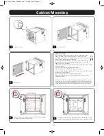
Page 4: ...n présentée dans ce manuel La plage de température de fonctionnement pour le coffret mural et ses accessoires est de 14 à 140 F 10 à 60 C Instructions de déballage Déballez le coffret en enlevant soigneusement le carton et les coins ondulés Inspecter le coffret et signaler les dommages en cas de dommage lié au transport Éviter d endommager le coffret lors du retrait de l emballage Dimension et le ...

Page 5: ...ners Install 2 fasteners through plywood into 2 x 4 wall studs spaced 16 on center Install enclosure onto fasteners Install remaining 2 fasteners though plywood into studs Make sure all 4 fasteners are installed through plywood into wall studs Tighten all fasteners For other wall types the installer must provide appropriate hardware The wall must be uniform flat structurally stable and has a struc...

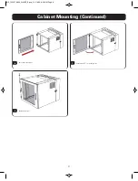
Page 6: ...4 1 Cabinet Mounting Continued 6 Reset door into hinges 7 8 Replace door pins Rotate door 90 to closed position INS_100 22796 00_WallMT_B qxp_A 2 18 20 8 34 AM Page 6 ...

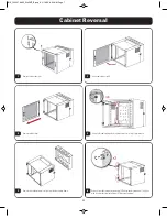
Page 7: ...s and lock washers using 13mm wrench Remove cabinet door 5 6 Remove front door hinges by removing 2 Phillips head screws and 1 4 20 nut with lock washer from each hinge 7 16 wrench required Remove the cabinet center section from the back plate frame 3 INS_100 22796 00_WallMT_B qxp_A 2 18 20 8 34 AM Page 7 ...

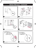
Page 8: ...in latch by removing 4 Phillips head screws and nylon locking nuts 5 5 mm wrench required 9 Re install 4 cabinet hinge bolts using 13mm wrench 10 Reset door into hinges 11 Remove cabinet handle from door by removing 3 Phillips head screws rotate handle 180 12 Re install handle onto door INS_100 22796 00_WallMT_B qxp_A 2 18 20 8 34 AM Page 8 ...

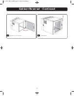
Page 9: ...Cabinet Reversal Continued 5 2 13 14 Replace door pins Rotate door 90 to closed position INS_100 22796 00_WallMT_B qxp_A 2 18 20 8 34 AM Page 9 ...

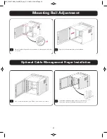
Page 10: ...il to desired depth and re install hardware 1 Recess front mounting rails at least 100mm 4 0 in using Step 1 above 2 Optional Cable Management Finger Installation Install cable management fingers and re secure mounting rails using mounting rail hardware shown above in Step 2 INS_100 22796 00_WallMT_B qxp_A 2 18 20 8 34 AM Page 10 ...

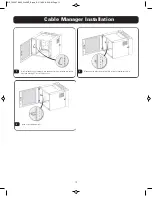
Page 11: ... managers into equipment rails by installing into square holes and rotating 45 into locking position 2 Managers may either be installed flush to front of equipment rails or 3 proud of the equipment rails INS_100 22796 00_WallMT_B qxp_A 2 18 20 8 34 AM Page 11 ...

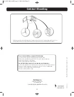
Page 12: ...g during a lightning storm Lors de l installation respectez les consignes de sécuritésuivantes A Utiliser avec prudence lors de l installation ou de la modification circuits de télécommunications B Ne jamais toucher les bornes de fil métallique non isolés sauf si le circuit a étédébranché C Ne jamais installer cet appareil dans un endroit humide D Ne jamais installer pendant un orage Bonding posts...

Reviews: