13
- Luminance processor: CVBS coming from video switches is internally applied to luminance processor, which is composed
of chrominance trap filter, luminance delay line and peaking circuits. Sharpness control modifies peaking by I2C.
- Black stretch circuit (pin 21): This feature of the picture is fixed (not adjustable). Black stretch capacitor 2250 is
connected to pin 21.
7.1.4 Chroma Decoding
- ACC and chroma filter: Video signal coming from video switches, goes through an internal variable-gain amplifier to the
chroma band pass filter. Gain of amplifier is determined by burst amplitude (ACC). If the amplitude of chroma signal is
higher than standard, an additional overload circuit decreases it (ACCO).
- XTAL (pin 40): The VCO uses one 4,43MHz crystal connected to pin40.
PAL sets:
STV2246 is used. Bandpass filter and demodulator are fully integrated.
Demodulator consist of synchronous detectors.
PLL is locked during the burst gate time window.
- CLPF (pin 41): The voltage on this chroma PLL filter controls the VCO in order to have the right frequency and
phase according burst signal.
PAL/ SECAM sets:
STV2248 is used. Pal or Secam signals are recognized automatically by the IC.
Pal decoding is the same as in STV2246.
Secam demodulation is based on a PLL with automatic calibration loop.
- Secam bell filter (pin 38): Central frequency of bell filter
(4.286 MHz)
is fine tuning during frame blanking, using
the XTAL frequency (
4.433 MHz) as a reference
. Tuning control voltage is stored in C2270.
- Chroma DL: The outputs of the demodulator are applied to an internal chroma delay line. Line number n is delayed
64useg and added to n+1 obtaining U and V signals (R-Y and B-Y).
7.1.5 RGB processor
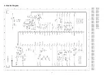
- External RGB inputs (pins 25, 26, 27): RGB inputs coming from scart (see diagram C), are AC coupled (C2291/92/93)
and converted internally in YUV signals (RGB TO YUV). Then are switched with internal YUV (YUV SWITCH) by fast
blanking.
- Fast blanking external (pin 28): When fast blanking is high external RGB is displayed, only if TV is in external AV
(program 0). Fast blanking can switch signals for full screen (by a DC voltage) or for a part of the screen (by a pulse
voltage).
- Matrix: After switching, YUV signals are converted to RGB in the internal MATRIX circuit. Saturation control is received
from the µC by I2C bus.
- APR (pin 24): The APR circuit (Automatic RGB Peak Regulation) compensates the spread of contrast between sources.
If one of RGB signals exceeds the APR threshold, 2440 is charged and the gain is decreased. APR threshold can be
adjusted in Service menu.
- RGB OSD (pins 36, 35, 34): RGB inputs for OSD and TXT coming from µC (7600 diagram E), are AC coupled (C2242/
43/44) and applied to a RGB SWITCH controlled for the µC by fast blanking input (pin 37).
Video controls: Contrast, brightness and saturation are adjusted by I2C for the µC.
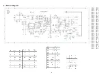
- BCL input (pin 46): Beam current is limited by circuit BCL/SAF. When beam current is high, voltage of C2460 is lower
(Diagram B), D6462 conducts and Vpin46 is lower. When Vpin46 < 5.75V first contrast and then brightness are reduced.
- Safety input (pin 46): BCL/SAF circuit has also a safety function. If frame deflection is broken down, T7431 conducts
(Diagram B), Vpin46 = 0V and line deflexion (pin 48) is disabled .
- RGB output circuit (pins 32, 31, 30): RGB outputs are drived to RGB amplifier (Diagram B).
- Digital cut-off loop (pin 33): Cut-off loop permits to control automatically the cut-off point of the 3 RGB cathodes by DC
level. At the end of the frame blanking 3 consecutive cut-off lines, B, G and R are created. Cut-off current flows across
T7204, T7209 and T7212 (Diagram B) respectively and it is measured on pin 33. When VG2 voltage is adjusted, DC level
of RGB outputs is adapted to keep cut-of current.
- Warm-up detection circuit (pin 33): At the start up picture is blanked and 3 white lines are drived, instead of cut-off lines.
As soon as the start beam current is detected on pin 33, RGB circuit starts in normal operation. If RGB circuit is
damaged or grid 2 is low, the RGB circuit could not start (black picture) due to current is not detected.
7.1.6 Horizontal synchro
- Start up (pins 45, 53): The horizontal oscillator starts running when supply voltage of pin 45 reaches 6V and supply
voltage of pin 53 reaches 4V. During start up circuit provides a softer operating horizontal output with a 75% of duty cycle.


