background image


Important Regulatory and Safety Notices 

Before using this product and any associated equipment, refer to the “Important Safety Instructions” 
listed below so as to avoid personnel injury and to prevent product damage.  

 Products may require specific equipment, and /or installation procedures be carried out to satisfy 
certain regulatory compliance requirements. Notices have been included in this publication to call 
attention to these Specific requirements. 

Symbol Meanings 


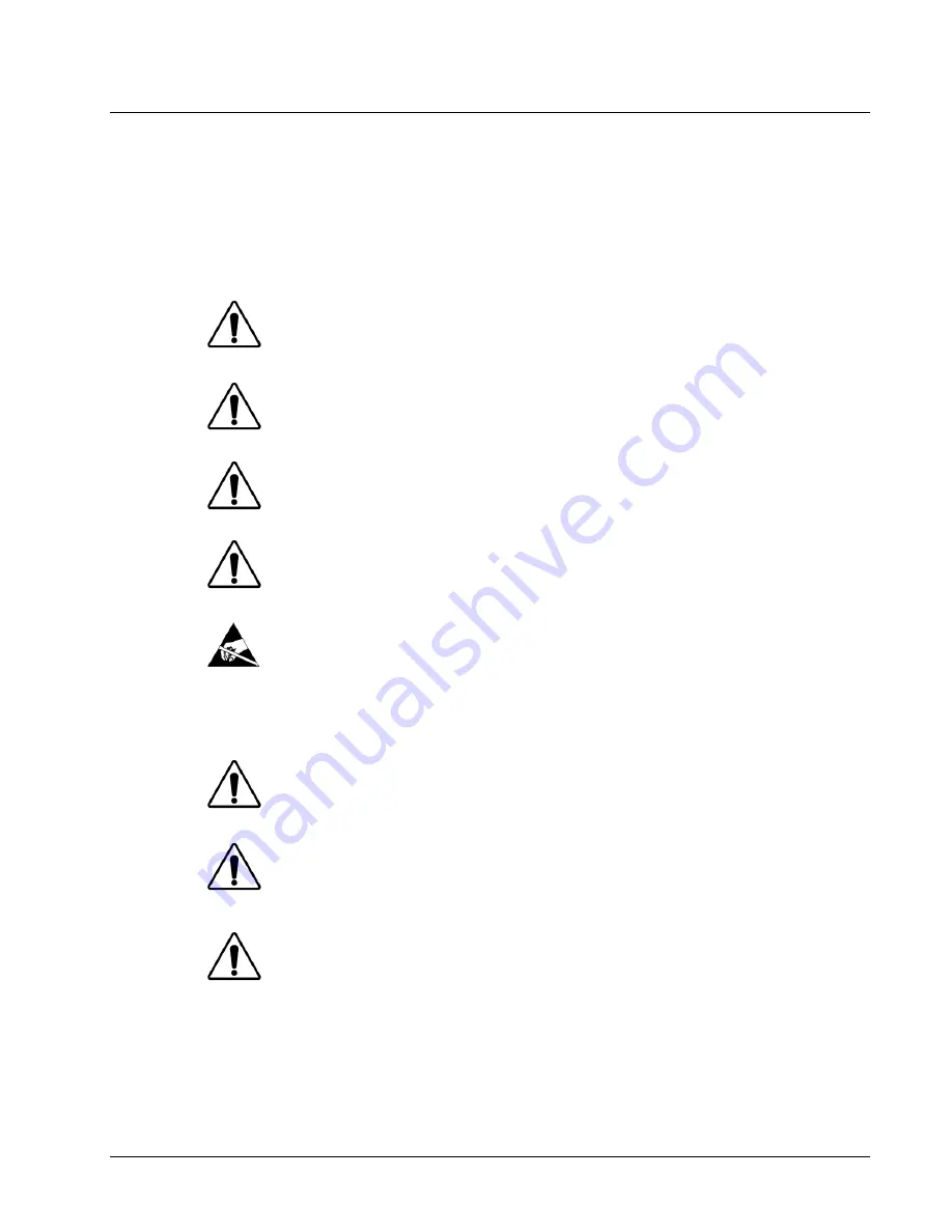
This symbol on the equipment refers you to important operating and maintenance 
(servicing) instructions within the Product Manual Documentation. Failure to heed 
this information may present a major risk of damage or injury to persons or 
equipment. 


Warning


The symbol with the word 

“Warning”

 within the equipment manual indicates a 

potentially hazardous situation, which if not avoided, could result in death or serious 
injury. 


Caution


The symbol with the word “

Caution

” within the equipment manual indicates a 

potentially hazardous situation, which if not avoided, may result in minor or 
moderate injury. It may also be used to alert against unsafe practices. 


Notice


The symbol with the word “

Notice

” within the equipment manual indicates a 

situation, which if not avoided, may result in major or minor equipment damage or a 
situation which could place the equipment in a non-compliant operating state.  


ESD 

Susceptibility


This symbol is used to alert the user that an electrical or electronic device or 
assembly is susceptible to damage from an ESD event.  

Important Safety Instructions 


Caution


This product is intended to be a component product of the openGear 8300 series 
frame. Refer to the openGear 8300 series frame User Manual for important safety 
instructions regarding the proper installation and safe operation of the frame as well 
as it’s component products.  


Warning


Certain parts of this equipment namely the power supply area still present a safety 
hazard, with the power switch in the OFF position. To avoid electrical shock, 
disconnect all A/C power cords from the chassis' rear appliance connectors before 
servicing this area. 


Warning


Service barriers within this product are intended to protect the operator and service 
personnel from hazardous voltages. For continued safety, replace all barriers after 
any servicing. 

This product contains safety critical parts, which if incorrectly replaced may present 
a risk of fire or electrical shock. Components contained within the product’s power 
supplies and power supply area, are not intended to be customer serviced and should 
be returned to the factory for repair. 

To reduce the risk of fire, replacement fuses must be the same type and rating. 

Only use attachments/accessories specified by the manufacturer. 

Summary of Contents for openGear UDA-8705A

Page 1: ...UDA 8705A Analog Utility Distribution Amplifier User Manual Part Number UDA 8705A OM Version 1 1 ...

Page 2: ...ial in this manual is furnished for informational use only It is subject to change without notice and should not be construed as a commitment by Sierra Video Sierra Video assumes no responsibility or liability for errors or inaccuracies that may appear in this manual Trademarks is a registered trademark of Ross Video is a registered trademark of Sierra Video DashBoard Control System is a registere...

Page 3: ... equipment damage or a situation which could place the equipment in a non compliant operating state ESD Susceptibility This symbol is used to alert the user that an electrical or electronic device or assembly is susceptible to damage from an ESD event Important Safety Instructions Caution This product is intended to be a component product of the openGear 8300 series frame Refer to the openGear 830...

Page 4: ...anadian ICES 003 Cet appareil numerique de classe A est conforme à la norme NMB 003 du Canada EUROPE This equipment is in compliance with the essential requirements and other relevant provisions of CE Directive 93 68 EEC INTERNATIONAL This equipment has been tested to CISPR 22 1997 along with amendments A1 2000 and A2 2002 and found to comply with the limits for a Class A Digital device Notice Thi...

Page 5: ...ral resources Sierra Videoencourages you to use the appropriate take back systems These systems will reuse or recycle most of the materials from your end of life equipment in an environmentally friendly and health conscious manner The crossed out wheeled bin symbol invites you to use these systems If you need more information on the collection reuse and recycling systems please contact your local ...

Page 6: ......

Page 7: ... 2 Board Installation 2 3 BNC Labels 2 3 Cable Connections 2 3 User Controls 3 1 In This Chapter 3 1 Jumper Locations 3 2 LEDs 3 2 Button Controls 3 3 Control and Monitoring 4 1 In This Chapter 4 1 DashBoard Control System 4 1 SNMP Monitoring and Control 4 3 Specifications 5 1 In This Chapter 5 1 Service Information 6 1 In This Chapter 6 1 Troubleshooting Checklist 6 1 Power LED Conditions 6 2 Boo...

Page 8: ...ii Contents UDA 8705A User Manual Rev 1 1 ...

Page 9: ... please contact us at the numbers listed on the back cover of this manual Our technical support staff is always available for consultation training or service Overview The UDA 8705A is an analog general purpose distribution amplifier It is very useful in digital systems when there is a requirement for the distribution of a few analog signals such as a color black reference The UDA 8705A is a gener...

Page 10: ...l Block Diagrams This section includes functional block diagrams to illustrate the UDA 8705A functions including the looping feature Figure 1 Simplified Block Diagram of UDA 8705A Functions Figure 2 Simplified Block Diagram of UDA 8705A with Looping Function ...

Page 11: ...e warranty Documentation Terms The following terms are used throughout this guide Frame refers to the DFR 8300 series frame that houses the UDA 8705A card as well as any openGear frames All references to the DFR 8300 series frame includes versions of the 10 slot DFR 8310 and 20 slot DFR 8320 frames and any available options Operator and User both refer to the person who uses the UDA 8705A Board an...

Page 12: ...1 4 Introduction UDA 8705A User Manual Rev 1 1 ...

Page 13: ...e following note ESD Susceptibility Static discharge can cause serious damage to sensitive semiconductor devices Avoid handling circuit boards in high static environments such as carpeted areas and when wearing synthetic fiber clothing Always exercise proper grounding precautions when working on circuit boards and related equipment Unpacking Unpack each UDA 8705A you received from the shipping con...

Page 14: ...s R2 8705 or R2L 8705 are required Installing the Rear Module If you received a Rear Module with your UDA 8705A you will need to install the module in your DFR 8300 series frame before you can install the UDA 8705A in the frame or connect cables to the slot you have chosen for the UDA 8705A Skip this section if you are installing the UDA 8705A in a DFR 8310 BNC frame or the Rear Module is already ...

Page 15: ...rear connection plugs are properly seated on the midplane and rear modules This completes the procedure for installing the UDA 8705A in an DFR 8300 series frame BNC Labels Affix the supplied BNC label as per the included instructions to the BNC area on the rear of the rack frame Cable Connections This section provides instructions for connecting cables to the installed Rear Modules on your DFR 830...

Page 16: ...tting JP1 to TERM Refer to Figure 4 for cable connections R2L 8705 Full Rear Module with Looping Each card occupies two slots and provides eight outputs plus one looping output If the input is looped on the rear module to another device JP1 must be set to LOOP If looping is not used either set JP1 to TERM or terminate the input externally at BNC2 Refer to Figure 5 R2S 8705 Split Rear Module Each c...

Page 17: ...UDA 8705A User Manual Rev 1 1 User Controls 3 1 User Controls In This Chapter This chapter includes the following sections Jumper Locations LEDs Button Controls ...

Page 18: ...options TERM Install the jumper in this position to terminate the input signal on this card This is the default setting LOOP Install the jumper in this position to leave the input unterminated For example configure this setting if you wish to loop the signal to another device RV2 Gain Adjustment The rotation of RV2 adjusts the Gain level of the UDA 8705A and provides a gain range of 3dB LEDs The f...

Page 19: ...deo input signal is present on BNC 1 AES OTHER If the AES OTHER LED is lit a valid AES signal or some other analog signal is present on the input The signal must be greater than 0 5Vp p Note Slowly changing or small amplitude signals will pass through the card but the LEDs may be unlit In this case it is recommended to disable the Notify on Input Loss option via DashBoard Note that the Input Signa...

Page 20: ...3 4 User Controls UDA 8705A User Manual Rev 1 1 ...

Page 21: ...om a computer DashBoard communicates with other cards in the DFR 8300 series frame through the MFC 8310 N Network controller card This card is required in order to use DashBoard to configure the UDA 8705A The DashBoard software and manual can be downloaded from the Sierra Video website Using the Menus You must first install the DashBoard Control System on your computer Refer to the DashBoard User ...

Page 22: ... memory available EE Bank Storage count Signal Read only Signal Status Green Video Present Card is passing valid analog video Green AES Other Card is passing AES audio or other analog signal Green No input No input present or the signal is below the detection threshold The Notify on Loss of Input option is disabled Red No input No input present or the signal is below 0 5V p p The Notify on Loss of...

Page 23: ... the loss of input This is the default setting SNMP Monitoring and Control The MFC 8310 N Network Controller card in the DFR 8300 series frame provides optional support for remote monitoring and control of your frame and UDA 8705A using Simple Network Management Protocol SNMP which is compatible with many third party monitoring and control tools Refer to your UDA 8705A Management Information Base ...

Page 24: ...4 4 Control and Monitoring UDA 8705A User Manual Rev 1 1 ...

Page 25: ...UDA 8705A User Manual Rev 1 1 Specifications 5 1 Specifications In This Chapter This chapter includes the Technical Specifications for the UDA 8705A ...

Page 26: ...lation 51dB to 5MHz 40dB to 20MHz DC Offset 30mV Frequency Response 0 08dB to 10MHz 0 2dB to 20MHz Differential Phase 0 1 in NTSC 0 3 in PAL Differential Gain 0 1 in NTSC 0 1 in PAL RMS Noise unweighted 68dB Performance all outputs loaded Gain Range 3dB Gain Stability 0 2 per 10 C Delay 7ns 9 3 58MHz NTSC 7ns 11 4 43MHz PAL Chrominance to Luminance Delay 2 0ns Line Rate Window Tilt 0 1 Field Rate ...

Page 27: ...y associated peripheral equipment for signs of trouble 2 Power Check Check the power indicator LED on the distribution frame front panel for the presence of power If the power LED is not illuminated verify that the power cable is connected to a power source and that power is available at the power main Confirm that the power supplies are fully seated in their slots If the power LED is still not il...

Page 28: ...suitability of Sierra Video Systems hereinafter SVS products for Buyer s intended use No product sold by SVS is designed or manufactured for use in any manner or under any conditions other than those described in SVS s instruction manuals and other printed material for each particular product If any product is used or applied in a manner or under conditions not specifically authorized by such writ...

Page 29: ...ocable to the goods which give rise to such claim 3 In no event shall SVS be liable for any damages or injuries to person or property if any goods do not meet the above limited warranty including without limitation incidental expenses or consequential or special damages except as set forth in such limited warranty The foregoing states the exclusive remedy of Buyer and the exclusive liability of SV...

Page 30: ...Department Contact information is supplied at the end of this publication A Return Material Authorization number RMA will be issued to you as well as specific shipping instructions should you wish our factory to repair your UDA 8705A If required a temporary replacement module will be made available at a nominal charge Any shipping costs incurred will be the responsibility of you the customer All p...

Page 31: ...UDA 8705A User Manual Rev 1 1 Service Information 6 5 ...

Page 32: ......

Page 33: ... Utility Distribution Amplifier User Manual additional R1 8705 openGear Rear Module for the DFR 8310 series frames R1L 8705 openGear Rear Module with Looping for the DFR 8310 series frames DFR 8310 N Digital Products Frame and Power Supply with cooling fans and MFC 8310 N card 2RU holds up to 10 cards DFR 8320 CNS Digital Products Frame Power Supply Cooling Fans MFC 8310 N COMM I O Module and SNMP...

Page 34: ......

Page 35: ...upport 530 478 1000 After hours Emergency 530 888 3195 Fax 530 478 1105 E MAIL General Information Service sierravideo com Technical Support techsupport sierravideo com POSTAL SERVICE Sierra Video 104B New Mohawk Rd Nevada City CA 95959 Sierra Video Incorporated PO Box 2462 Grass Valley CA 95945 Visit Us Please visit us at our website for Company information Related products and full product lines...

Reviews: