AirLink MG90 Hardware User Guide
Rev 3 Feb.17
33
4118699
Serial Port
•
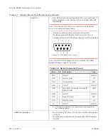
9-pin RS-232 serial port configured as DTE, connects directly to
most computers or other devices with a null-modem cable with
handshaking
Note: If you have a DTE device, you need to use a null modem
(cross-over) cable with handshaking.
•
Used for connecting serial devices and configuration
•
Provides access to MG90’s four GPIOs via pins 1, 4, 6, 9
•
Complies with the EIA RS-232D specification for DTE equipment
Figure 3-2: DB-9 Male Serial Connector
Note: An RS-232 GPIO Breakout Cable is available. See
on page 50 for details.
SIM Card Interface
•
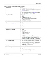
Four mini-SIM (2FF) slots—Two for each installed radio module
•
1.8 V/3.3 V.
•
This interface is compliant with the applicable 3GPP standards
for USIM.
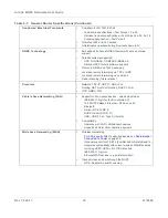
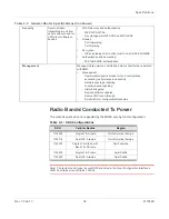
Table 3-1: General Router Specifications (Continued)
1
2
3
4
5
6
7
8
9
Table 3-2: Serial Connector Pin-out
Name
Pin
Description
Type
DCD
1
GPIO4
a
a.
GPIO pins are digital input only. Digital output to be supported by
future software update.
IN/OUT
RXD
2
Receive Data
IN
TXD
3
Transmit Data
OUT
DTR
4
GPIO2
IN/OUT
GND
5
Main GND. Connected internally to
BOARD GND
GND
DSR
6
GPIO3
IN/OUT
RTS
7
Ready To Send
OUT
CTS
8
Clear To Send
IN
RI
9
GPIO1
IN/OUT

