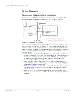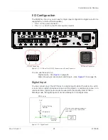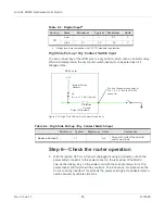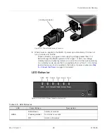
Installation and Startup
Rev 3 Feb.17
12
4118699
4.
The MG90 is ready for use. However, you should further configure the unit using
the sections provided in this document.
Tools and Materials Required
•
SIM card(s) (provided by your mobile network operator)—Depending on your
device configuration, you will have one or two cellular modems. Each modem can
support up to two SIM cards.
•
#1 Phillips screwdriver
•
Laptop computer with Ethernet cable
•
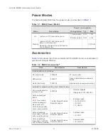
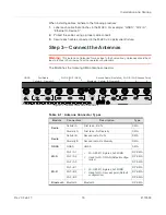
Multi-element antenna(s) appropriate for your MG90. See
on page 9 for
suggested antennas.
•
SMA wrench (provided with MG90)
•
AC or DC power cable (available from Sierra Wireless or use your own custom
cable). See
on page 9 for part numbers.
•
Optional—9-pin connection cable for the RS-232 port
Caution:
The MG90 has a hardened case for use in extreme environments. If the MG90 is to
be used in these environments, make sure to use cables designed and specified for this use to
avoid cable failure.
Installation Overview
The steps for a typical installation are performed as follows:
•
•
Step 2—Mounting and Grounding the MG90 Chassis
•
•
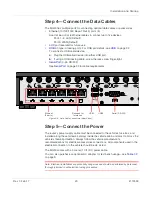
Step 4—Connect the Data Cables
•
•
Step 6—Check the router operation
•
Step 7—Startup and Software Configuration
Note: Depending on where you are installing the MG90, you may want to mount the router
before connecting the antenna, cables and power.
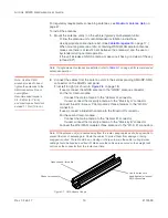
Step 1—Insert the SIM Cards
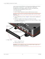
The MG90 has four mini-SIM (2FF) card slots—two slots for each radio module (up to
two radios). The card slots are located behind a removable plate on the front of the
device as shown in
From left to right, the “SIM Card” slots are:
•
A1—First radio module (Cellular A), first SIM
•
A2—First radio module (Cellular A), second SIM
•
B1—Second radio module (Cellular B), first SIM
•
B2—Second radio module (Cellular B), second SIM

