Installation and Startup
Rev 3 Feb.17
18
4118699
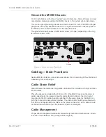
When installing cables, adhere to the following practices:
1.
Label each cable that attaches to the MG90. For example: “GNSS”, “Wi-Fi A”,
“Ethernet to Device X”.
2.
Protect the cables using a proper cable conduit.
3.
Secure each cable connected to the MG90 via a permanent fixture.
Step 3—Connect the Antennas
Warning:
This router is not intended for use close to the human body. Antennas should be at
least 8 inches (20 cm) away from the operator or bystanders.
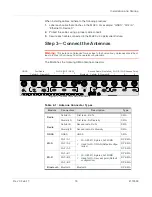
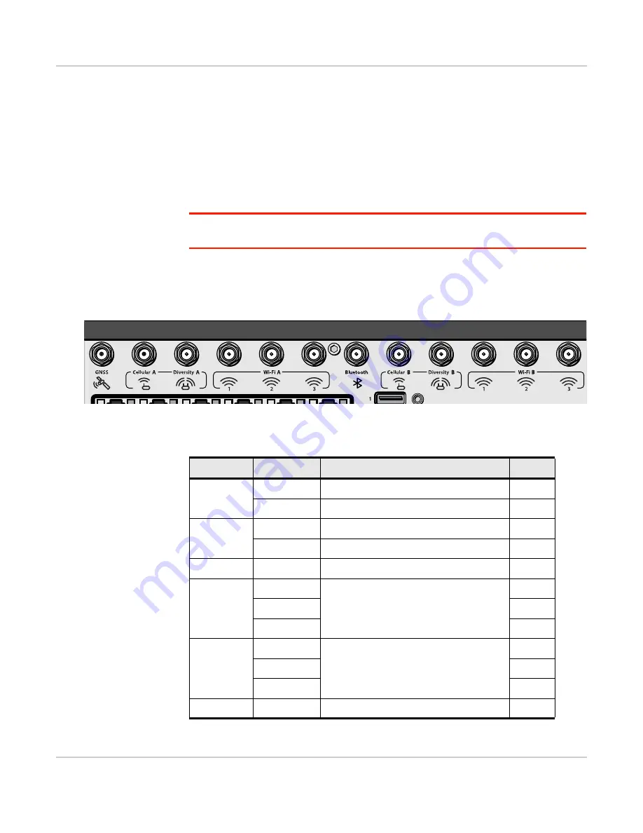
The MG90 has the following SMA antenna connectors:
Figure 2-6: Antenna Connectors (Rear Panel)
GNSS
Cellular A Diversity A
Wi-Fi A (Wi-Fi WAN)
Bluetooth
Cellular B Diversity B
Wi-Fi B (Wi-Fi Access Point)
First Radio
Second Radio (if installed)
1
2
3
1
2
3
Table 2-1: Antenna Connector Types
Module
Connectors
Description
Type
Radio
Cellular A
First radio, Rx/Tx
SMA
Diversity A
First radio, Rx Diversity
SMA
Radio
Cellular B
Second radio, Rx/Tx
SMA
Diversity B
Second radio, Rx Diversity
SMA
GNSS
GNSS
GNSS
SMA
Wi-Fi
Wi-Fi A 1
•
Wi-Fi 802.11b/g/n/ac, 3x3 MIMO
•
Used for Wi-Fi WAN (Default configu-
ration)
RP-SMA
Wi-Fi A 2
RP-SMA
Wi-Fi A 3
RP-SMA
Wi-Fi
Wi-Fi B 1
•
Wi-Fi 802.11b/g/n/ac, 3x3 MIMO
•
Used for Wi-Fi access point (Default
configuration)
RP-SMA
Wi-Fi B 2
RP-SMA
Wi-Fi B 3
RP-SMA
Bluetooth
Bluetooth
Bluetooth
RP-SMA

