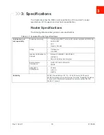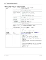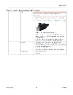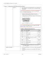
AirLink MG90 Hardware User Guide
Rev 3 Feb.17
23
4118699
Wiring Diagrams
Recommended Basic Vehicle Installation
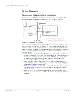
For most vehicle installations, Sierra Wireless recommends connecting the white
Ignition Sense wire to the vehicle’s ignition switch, as shown in
Figure 2-10: Recommended Vehicle Installation
The recommended vehicle installation allows the router to operate with the vehicle.
When the vehicle ignition is off, the MG90 is in standby mode. If desired, you can
configure a delay between the time the vehicle’s ignition shuts off, and the time the
router shuts down. A delayed shutdown is especially useful if you want to maintain a
network connection while the vehicle’s engine is shut off for short periods, such as in
a delivery vehicle.
•
Pin 1 (Power) —Use the red wire in the DC cable to connect Pin 1 to the power
source. Include a 9 A, fast blow fuse, recommended to have no more than ± 10%
de-rating over the operating temperature range, in the input power line. Sierra
Wireless recommends using a continuous (unswitched) DC power source.
Connect the power through the vehicle’s fuse box.
•
Pin 2 (Ground)—Use the black wire in the DC cable to connect Pin 2 to the
vehicle battery’s negative terminal, or ground. See also
•
Pin 3 (Ignition Sense) —Sierra Wireless recommends always using the Ignition
Sense wire (Pin 3) to turn the router off. It should not be turned off by discon-
necting the power.
•
Pin 4 (GPIO)—This pin can remain unconnected if GPIO functionality is not
required. Otherwise, connect the GPIO as described in the
MG90 power plug
Power (Red wire)
Ignition Sense (White wire)
I/O (Green wire)
Ground (Black wire)
-
+
Battery
Ignition
1
3
4
2
Engine compartment
Vehicle cabin
Vehicle firewall
Vehicle fuse box
9 A fuse
Note: If the I/O pin is not used, leave the
green wire unterminated.

