Installation and Startup
Rev 3 Feb.17
24
4118699
I/O Configuration
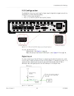
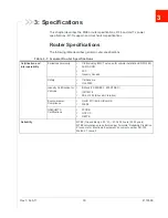
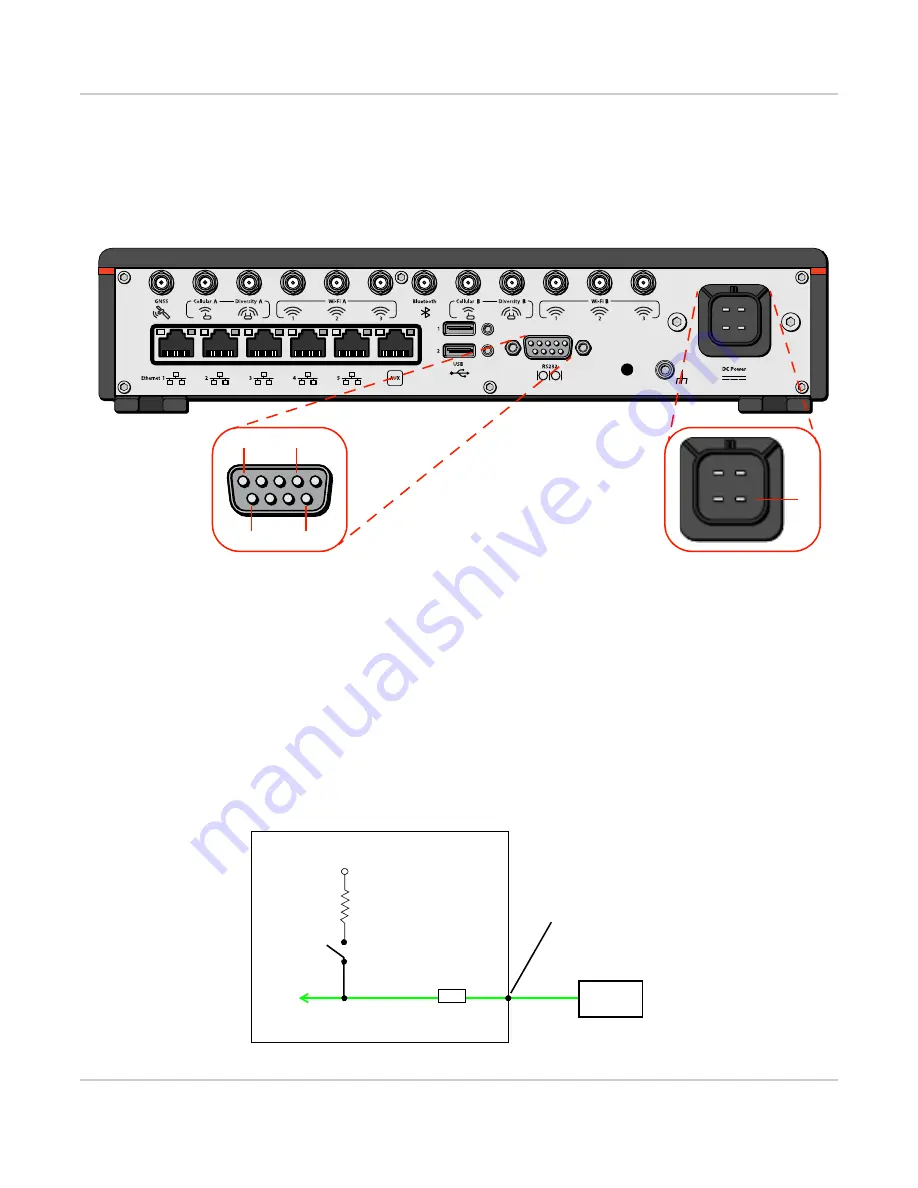
The MG90 has five pins you can use for digital input configuration (digital output to be
supported by a future software update):
•
Pin 4 on the power connector
•
Pins 1, 4, 6, and 9 on the RS-232 serial connector
Figure 2-11: I/O Pin-out for RS-232 Connector and Power Connector
You can use these pins as:
·
Digital inputs—See
·
High side pull-ups/dry contact switch inputs—See
Digital Input
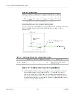
You can connect any of the GPIO pins to a digital input to detect the state of a switch,
or to monitor an external device such as a motion detector, a remote solar panel, or a
remote camera. Digital input can also be used with the standby timer. While in
Standby mode, the digital input will not be acted upon if it changes state.
Figure 2-12: Digital Input
4
DC Power Connector
RS-232 Connector
1
4
6
9
MG90 router
Off (default)
3.3V
V
High
2.1 V
Protection
circuitry
Internal Pull-up
Resistor
Digital
input
Pin 4 on the power connector, or
Pin 1, 5, 6, or 9 on the RS-232
connector


