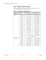
AirLink MG90 Hardware User Guide
Rev 3 Feb.17
25
4118699
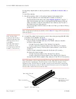
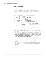
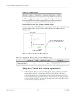
High Side Pull-up / Dry Contact Switch Input
You can connect any of the GPIO pins to a dry contact switch, such as an alarm relay.
While in Standby mode, the dry contact switch input will not be acted upon if it
changes state.
Figure 2-13: High Side Pull-up / Dry Contact Switch Input
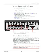
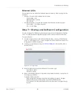
Step 6—Check the router operation
1.
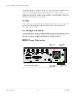
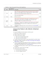
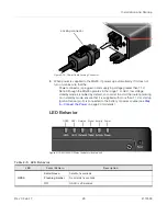
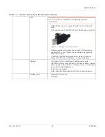
With the ignition OFF (or AC power unplugged if using an adapter), attach the
power cable connector to the power socket on the rear panel of the MG90.
Line up the locking ‘key’ on the power cord with the corresponding slot on the
power socket and fully insert the connector. The lock snaps into place when the
cord is correctly inserted. This protects the power cord against accidental discon-
nection caused by vehicle vibrations.
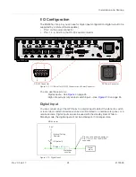
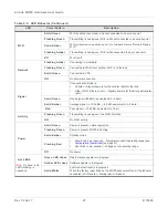
Table 2-3: Digital Input
a
a.
Voltage levels are compatible with 3.3V TTL standard logic families.
Pull-up
State
Minimum
Typical
Maximum
Units
Off
Low
—
—
0.7
V
High
2.1
3.3
36
V
MG90 router
On
3.3V
I
Source
= 1.1 mA (Typical)
Protection
circuitry
Internal Pull-up
Resistor
Output Off (default)
Pin 4 on the power connector, or
Pin 1, 5, 6, or 9 on the RS-232
connector
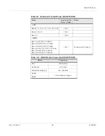
Table 2-4: High Side Pull-up / Dry Contact Switch Input
Minimum
Typical
Maximum
Units
Comments
Source Current
-
1.1
-
mA
Amount of current the external
switch must sink

