Rev 2.0 Mar.10
27
4
4: Hardware Installation of the PinPoint X
•
•
•
•
Note: During installation,
please be sure that the
cables are secure but do
not bear any additional
weight that could loosen
the connector from the
unit.
Your PinPoint X should be mounted in a position that allows easy
access for the cables so they are not bent, constricted, in close
proximity to high amperage, or exposed to extreme temperatures.
The LEDs on the front panel should be visible for ease of operational
verification. You should ensure that there is adequate airflow around
the modem but that it is kept free from direct exposure to the
elements, such as sun, rain, dust, etc.
Caution:
The PinPoint X is in a hardened case and designed for use in
industrial and extreme environments. However, unless you are using cables
expressly designed for such environments, they can fail if exposed to the
same conditions the PinPoint X can withstand.
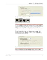
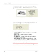
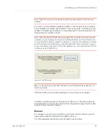
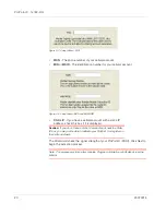
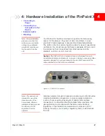
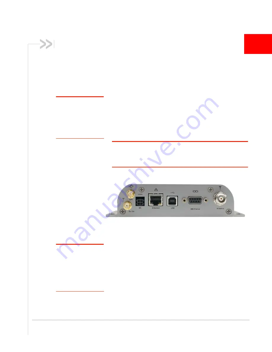
Figure 4-1: PinPoint X Connectors
Note: This device is not
intended for use within
close proximity of the
human body. Antenna
installation should provide
for at least a 20 CM
separation from the
operator.
Antennas selected should not exceed a maximum gain of 5 dBi under
standard installation configuration. In more complex installations
(such as those requiring long lengths of cable and/or multiple
connections), it’s imperative that the installer follow maximum dBi
gain guidelines in accordance with the radio communications
regulations of the Federal Communications Commission (FCC),
Industry Canada
, or
your country’s regulatory body (if used outside
the US).
Summary of Contents for AirLink PinPoint X
Page 2: ...PinPoint X for Verizon User Guide 20070914 Rev 2 0...
Page 3: ......
Page 7: ...PinPoint X 1x EV DO iv 20070914...
Page 11: ...PinPoint X 1x EV DO viii 20070914...
Page 21: ...PinPoint X 1x EV DO 10 20070914...
Page 45: ...PinPoint X 1x EV DO 34 20070914...
Page 51: ...PinPoint X 1x EV DO 40 20070914...
Page 61: ...PinPoint X 1x EV DO 50 20070914...
Page 62: ......

