AirLink RV50 Series Hardware User Guide
36
4117313
Digital Input
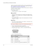
You can use the green wire to connect Pin 4 to a digital input to detect the state of
a switch such as a vehicle ignition, or to monitor an external device such as a
motion detector, a remote solar panel, or a remote camera. Digital input can also
be used with the standby timer.
Figure 3-10: Digital Input
RV50
Series gateway
Off (default)*
Pin 4
V
in
V
High
≥
2.7 V
Protection
circuitry
Internal Pull-up
Resistor
Output Off (default)*
* Configurable on the ACEmanager I/O tab
Digital
input
Table 3-5: Digital Input
Pull-up
State
Minimum
Typical
Maximum
Units
Off
Low
—
—
1.0
V
High
2.7
—
Vin
V
Summary of Contents for AirLink RV50 Series
Page 1: ...AirLink RV50 Series Hardware User Guide 4117313 Rev 3 ...
Page 2: ......
Page 6: ...AirLink RV50 Series Hardware User Guide 6 4117313 ...
Page 10: ...AirLink RV50 Series Hardware User Guide 10 4117313 ...
Page 18: ...AirLink RV50 Series Hardware User Guide 18 4117313 ...
Page 50: ...AirLink RV50 Series Hardware User Guide 50 4117313 ...
Page 62: ...AirLink RV50 Series Hardware User Guide 62 4112895 ...
Page 66: ...AirLink RV50 Series Hardware User Guide 66 4117313 ...
Page 77: ......
Page 78: ......

