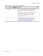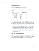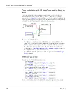
Installation and Startup
Rev 3 Dec.16
37
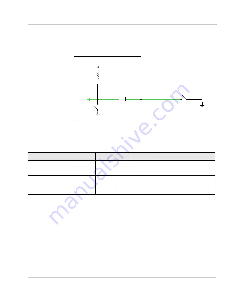
High Side Pull-up / Dry Contact Switch Input
You can use the green wire to connect Pin 4 to a dry contact switch. The dry
contact switch is not available in Standby mode.
Figure 3-11: High Side Pull-up / Dry Contact Switch Input
RV50
Series gateway
On**
Pin 4
V
in
*
*
Depending on the load, this value can range from Vin to Vin - 2.5 V.
I
Source
= 1.1 mA (Typical)
Protection
circuitry
Internal Pull-up
Resistor
Output Off (default)**
** Configurable on the ACEmanager I/O tab
Table 3-6: High Side Pull-up / Dry Contact Switch Input
Minimum
Typical
Maximum
Units
Comments
Source Current
0.6
Vin = 7 V
1.1
Vin = 12 V
3.5
Vin = 36 V
mA
Maximum current the voltage
output can provide (depends on
Vin)
V
out
V
in
- 2.5
—
V
in
V
The voltage on Pin 4 when the
high side pull-up is enabled
(depends on Vin and power
consumption)
Summary of Contents for AirLink RV50 Series
Page 1: ...AirLink RV50 Series Hardware User Guide 4117313 Rev 3 ...
Page 2: ......
Page 6: ...AirLink RV50 Series Hardware User Guide 6 4117313 ...
Page 10: ...AirLink RV50 Series Hardware User Guide 10 4117313 ...
Page 18: ...AirLink RV50 Series Hardware User Guide 18 4117313 ...
Page 50: ...AirLink RV50 Series Hardware User Guide 50 4117313 ...
Page 62: ...AirLink RV50 Series Hardware User Guide 62 4112895 ...
Page 66: ...AirLink RV50 Series Hardware User Guide 66 4117313 ...
Page 77: ......
Page 78: ......

