Installation and Startup
Rev 3 Dec.16
27
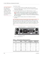
Step 3 — Connect the Data Cables
The RV50
Series gateway
has three ports for connecting data cables:
•
(Micro-AB)
•
Use a Cat 5e or Cat 6 Ethernet cable to connect the
•
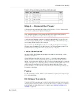
(9-pin RS-232)
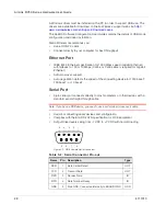
USB Port
Warning:
Do not use the USB port in a potentially explosive environment.
•
Complies with USB Version 2.0 for high speed operation
•
Can be configured to operate in one of two modes:
· Virtual Ethernet Port
: The RV50
Series gateway
behaves as if the PC were
connected to an Ethernet port, allowing access to the Internet and the
gateway
’s internal web server. This is the default setting.
· Virtual Serial Port
: The RV50
Series gateway
behaves as if it was
connected to a standard serial port. The primary use of this interface is for
the AT command line interface of ALEOS and for diagnostic access to the
radio module.
Note: By default, the USB port is configured as a virtual Ethernet port.
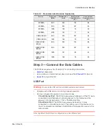
WCDMA
850
353
176
88
WCDMA
900
333
167
83
WCDMA
1900
158
79
39
WCDMA
2100
143
71
36
CDMA/EV-DO
800
375
187
94
CDMA/EV-DO
1900
158
79
39
GSM/GPRS/
EDGE
850
353
176
88
GSM/GPRS/
EDGE
900
333
167
83
GSM/GPRS/
EDGE
1800
167
83
42
GSM/GPRS/
EDGE
1900
158
79
39
Table 3-1: Recommended Antenna Separation
Service
Frequency
(MHz)
Wavelength (
λ)
(mm)
Best Antenna
Separation (mm)
(1/2
λ)
Good Antenna
Separation (mm)
(1/4
λ)
Summary of Contents for AirLink RV50 Series
Page 1: ...AirLink RV50 Series Hardware User Guide 4117313 Rev 3 ...
Page 2: ......
Page 6: ...AirLink RV50 Series Hardware User Guide 6 4117313 ...
Page 10: ...AirLink RV50 Series Hardware User Guide 10 4117313 ...
Page 18: ...AirLink RV50 Series Hardware User Guide 18 4117313 ...
Page 50: ...AirLink RV50 Series Hardware User Guide 50 4117313 ...
Page 62: ...AirLink RV50 Series Hardware User Guide 62 4112895 ...
Page 66: ...AirLink RV50 Series Hardware User Guide 66 4117313 ...
Page 77: ......
Page 78: ......


