AirLink RV50 Series Hardware User Guide
30
4117313
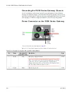
Grounding the RV50 Series Gateway Chassis
For DC installations (with a fixed “system” ground reference), Sierra Wireless
strongly recommends always grounding the RV50
Series gateway chassis to this
system ground reference. To ensure a good grounding reference, use a short wire
with a gauge of 18 AWG or larger connected to one of the mounting screws.
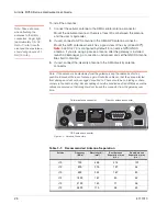
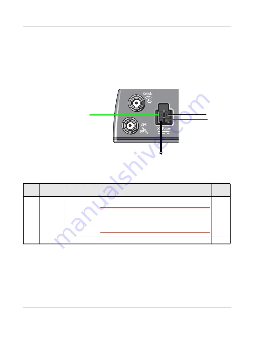
Power Connector on the RV50 Series Gateway
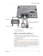
Figure 3-4: DC Power Cable Connections (Colors indicate DC cable wire colors.)
GPIO
Pin 4
Pin 3
Ignition
Pin 1
Power
Green
Red
White
Sense
Black
Pin 2
Ground
For more information, see wiring diagrams on
.
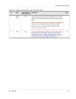
Table 3-3: Power Connector Pin and DC Cable Wires
Pin
Name
Associated DC
Cable Wire Color
Description
Type
1
Power
Red
Main power supply for device
Note: If you want to turn the RV50
Series gateway
on/off using a
control line, such as a vehicle ignition line, Sierra Wireless
strongly recommends that you connect the control/ignition line to
Pin 3 and apply continuous power on Pin 1.
PWR
2
Ground
Black
Main device ground
PWR
Summary of Contents for AirLink RV50 Series
Page 1: ...AirLink RV50 Series Hardware User Guide 4117313 Rev 3 ...
Page 2: ......
Page 6: ...AirLink RV50 Series Hardware User Guide 6 4117313 ...
Page 10: ...AirLink RV50 Series Hardware User Guide 10 4117313 ...
Page 18: ...AirLink RV50 Series Hardware User Guide 18 4117313 ...
Page 50: ...AirLink RV50 Series Hardware User Guide 50 4117313 ...
Page 62: ...AirLink RV50 Series Hardware User Guide 62 4112895 ...
Page 66: ...AirLink RV50 Series Hardware User Guide 66 4117313 ...
Page 77: ......
Page 78: ......


