background image

RV50 Series Specifications

Rev. 3 Apr. 13


61

Mechanical Specifications

Figure 4-1:  RV50 Series Gateway Mechanical Specifications

Weight: 320 g.

119.00 mm

94 mm

34 mm

Reset button

LEDs

Powe

r

Ac

tivity

Signal

Netwo

rk

SIM card panel

Cellular (RF) antenna connector

Power connector

Ethernet 

Serial (RS-232)

Rx Diversity

USB

GNSS

Mounting holes

Screws used to attach 
gateway cover

Underside view

Back view

Front view

Side view

3.70 in.

85 mm

3.35 in.

1.34 in.

4.69 in.

(11.3 oz.) 

Summary of Contents for AirLink RV50 Series

Page 1: ...AirLink RV50 Series Hardware User Guide 4117313 Rev 3 ...

Page 2: ......

Page 3: ...F The Sierra Wireless modem can transmit signals that could interfere with this equipment The driver or operator of any vehicle should not operate the Sierra Wireless modem while in control of a vehicle Doing so will detract from the driver or operator s control and operation of that vehicle In some states and provinces operating such communications devices while in control of a vehicle is an offe...

Page 4: ...ra Wireless and or its affiliates aggregate liability arising under or in connection with the Sierra Wireless product regardless of the number of events occurrences or claims giving rise to liability be in excess of the price paid by the purchaser for the Sierra Wireless product Patents This product may contain technology developed by or for Sierra Wireless Inc This product includes technology lic...

Page 5: ...mation Sales information and technical support including warranty and returns Web sierrawireless com company contact us Global toll free number 1 877 687 7795 6 00 am to 6 00 pm PST Corporate and product information Web sierrawireless com ...

Page 6: ...AirLink RV50 Series Hardware User Guide 6 4117313 ...

Page 7: ...ccessories 17 Warranty 17 Specifications at a Glance 19 Installation and Startup 23 Tools and Materials Required 23 Installation Overview 23 Step 1 Insert the SIM Cards 24 Step 2 Connect the Antennas 25 Step 3 Connect the Data Cables 27 Step 4 Connect the Power 29 Cable Strain Relief 29 Fusing 29 DC Voltage Transients 29 Grounding the RV50 Series Gateway Chassis 30 Power Connector on the RV50 Seri...

Page 8: ...unt 45 DIN Rail Mount 46 Reboot the RV50 Series Gateway 48 Reset the RV50 Series Gateway to Factory Default Settings 48 Recovery Mode 48 RV50 Series Specifications 51 Radio Frequency Bands 51 Radio Module Conducted Transmit Power 56 Carrier Aggregation Combinations 58 GNSS Technology 59 SIM Interface 60 Reliability Specifications 60 Mechanical Specifications 61 Regulatory Information 63 Important ...

Page 9: ...utput 68 AC Power Adapter Environmental Specifications 68 AC Power Adapter Reliability and Quality Control 69 AC Power Adapter Safety Standards 69 AC Power Adapter EMC Standards 69 AC Power Adapter Hazardous Substances 69 AC Power Adapter Energy Efficiency 70 Acronyms 71 Index 75 ...

Page 10: ...AirLink RV50 Series Hardware User Guide 10 4117313 ...

Page 11: ...ernet access to a mobile workforce The RV50 Series gateway has multiple communication ports including serial Ethernet and USB ports The power connector has one GPlO pin for remote monitoring and control and one ignition sense pin to turn the gateway on and off The RV50 is an LTE cellular gateway that supports a variety of radio band options including 3G HSPA or CDMA EV DO mobile broadband technolo...

Page 12: ...eporting to third party server platforms ALEOS Application Framework AAF offers real time onboard data processing Built in class leading voltage transient protection provides superior reliability and continuous operation E Mark and SAEJ1455 for shock and vibration Active GNSS for tracking equipment Preprogrammed low voltage disconnect to prevent battery drain Security via Remote Authentication RAD...

Page 13: ...iversity Antenna Connector Back Panel 9 pin RS 232 Serial Port USB 2 0 Micro AB Port See Ethernet Port on page 28 See Connect the Antennas on page 25 See Connect the Antennas on page 25 See Serial Port on page 28 See USB Port on page 27 Reset button See Reboot the RV50 Series Gateway and Reset the RV50 Series Gateway to Factory Default Settings on page 48 RJ 45 Ethernet Port GPS Antenna Connector ...

Page 14: ...ds For a complete list of AT Commands refer to the ALEOS Software Configura tion User Guide Power Modes The AirLink RV50 Series gateway has three power modes On The CPU and the radio are on The current draw is 900 mW 75 mA 12 VDC when the gateway is idle i e no traffic is being sent or received Standby The CPU and the radio are off but can be woken by an I O input or at a configured time Current d...

Page 15: ...ts If your use case does not require a Gigabit Ethernet connection choosing a slower rate results in substantial power savings When set to 10 or 100 Mbits both sides of the link must be set to the same fixed speed and duplex settings If you are unable to ensure that both sides of the link have exactly the same fixed settings it is best to use Auto Disable Serial Port Serial Port Configuration Disa...

Page 16: ...Power Saving Mode Powera Standby Mode 53 mW 4 4 mA Low Power Serial Idle Attached Disabled Enabled Disabled Disabled Enabled Enabled 885 mW 73 7 mA Low Power Ethernet Idle Attached 10 BaseT Full duplex Disabled Disabled Disabled Enabled Enabled 900 mW 75 mA Typical without Power Saving Features Attached and connected 20 dBm LTE 100 BaseT Full duplex Enabled Idle Enabled Idle Enabled Active antenna...

Page 17: ...led in the Primary SIM card slot the gateway uses the firmware associated with the SIM card in the Secondary SIM card slot This feature which is intended for North American products makes it possible to use a single hardware variant on multiple operator networks Accessories The following items come with the RV50 Series gateway DC power cable Mounting screws Quick Start Guide The following items ca...

Page 18: ...AirLink RV50 Series Hardware User Guide 18 4117313 ...

Page 19: ...ity Emissions Immunity CE Including EMC Test case for vehicle installation EN302489 ACMA RCM FCC Industry Canada Safety CB Scheme UL 60950 Industry Certification for Vehicles E Mark UN ECE Regulation 10 04 ISO7637 2 SAE J1455 Shock Vibration Environmental Compliance RoHS 2011 65 EU RoHS 2 WEEE REACH Halogen free PCB Hazardous Environments Class 1 Div 2 and Class I Zone 2 C22 2 No 213 Canada and IS...

Page 20: ...A 2A 2001 test categories 1 4 5 and 6 Mobile Network Operator Certification RV50 Pending for the RV50X Verizon Wireless AT T Sprint T Mobile USA US Cellular Rogers Bell Telus Network Technology See Radio Frequency Bands on page 51 Host Interfaces 10 100 1000 Base T RJ 45 Ethernet RS 232 serial port USB 2 0 Micro AB connector 3 SMA antenna connectors LTE Diversity Active GNSS SIM Card Interface Two...

Page 21: ...ngs DIN rail mount screws for attaching the RV50 to the DIN rail 1 1 N m 10 in lb Antennas Finger tight 5 7in lb is sufficient and the max torque should not go beyond 1 1 N m 10 in lb Operating Voltage Input voltage 7 36V Maximum ripple voltage to guarantee analog input accuracy 100 mVpp Power Consumption See page 16 GNSS Technology For GNSS bias information see GNSS Technology on page 59 Channels...

Page 22: ...ations to run on the RV50 and leverage the AirLink M2M Cloud platform Lua language coding platform Remote application management Eclipse based IDE Integrated real time debugging VPN IPSec GRE and SSL Tunnel VPN clients Up to 5 VPN tunnels IKE encryption Security Port Forwarding Port Filtering DMZ Trusted IPs MAC Filtering Authentication LDAP RADIUS TACACS Events Reporting Event Types digital input...

Page 23: ...tor 1 Phillips screwdriver if you are installing the SIM card Laptop computer with Ethernet cable Cellular antenna Optional GPS antenna Recommended diversity antenna AC or DC power cable available from Sierra Wireless or use your own custom cable Optional a 9 pin connection cable for the RS 232 port Optional DIN Rail Mounting Bracket kit available from Sierra Wireless Caution The gateway has a har...

Page 24: ...s the Primary SIM card If you are using only one SIM card Sierra Wireless recommends that you install it in Slot 1 If the SIM card or SIM cards have not already been installed insert the SIM cards into the gateway before connecting any external equipment or power to the gateway To install the SIM cards 1 Use a 1 Phillips screwdriver to remove the SIM card cover 2 Orient the SIM card s as shown in ...

Page 25: ...m Antenna Gain on page 64 Note The antenna should not exceed the maximum gain specified in RF Exposure on page 63 In more complex installations such as those requiring long lengths of cable and or multiple connections you must follow the maximum dBi gain guidelines specified by the radio communications regulations of the Federal Communications Commission FCC Industry Canada or your country s regul...

Page 26: ...on Advanced and set the GNSS Antenna Bias field to Disable 3 If used connect the diversity antenna to the SMA diversity antenna connector Note If the antenna is located away from the gateway keep the cables as short as possible to prevent the loss of antenna gain Route the cables so that they are protected from damage and will not be snagged or pulled on There should be no binding or sharp corners...

Page 27: ...ternet and the gateway s internal web server This is the default setting Virtual Serial Port The RV50 Series gateway behaves as if it was connected to a standard serial port The primary use of this interface is for the AT command line interface of ALEOS and for diagnostic access to the radio module Note By default the USB port is configured as a virtual Ethernet port WCDMA 850 353 176 88 WCDMA 900...

Page 28: ...s required for Gigabit Ethernet Auto crossover support Auto negotiation detects the speed of the connecting device for 1000 baseT 100 baseT or 10 baseT Serial Port 9 pin serial port connects directly to most computers or other devices with a standard serial straight through cable Note If you have a DCE device you need to use a null modem cross over cable Used for connecting serial devices and conf...

Page 29: ...ronments Place the cable strain relief within 200 mm 8 of the RV50 Series gateway to reduce the mass of cable supported by the power connector under vibration Ideally the strain relief mounting for the DC cable should be attached to the same object as the gateway so both the gateway and cable vibrate together The strain relief should be mounted such that it does not apply additional stress on the ...

Page 30: ...teway Figure 3 4 DC Power Cable Connections Colors indicate DC cable wire colors GPIO Pin 4 Pin 3 Ignition Pin 1 Power Green Red White Sense Black Pin 2 Ground For more information see wiring diagrams on page 32 Table 3 3 Power Connector Pin and DC Cable Wires Pin Name Associated DC Cable Wire Color Description Type 1 Power Red Main power supply for device Note If you want to turn the RV50 Series ...

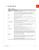
Page 31: ...sitive terminal of your power supply or battery If you are using a Sierra Wireless AC adapter the connection is inside the cable I 4 GPIO Green User configurable digital input output or analog voltage sensing input Connect to switch relay or external device For more information see Pin 4 GPIO Use the green wire for I O configurations See I O Configuration on page 34 on page 34 and the ALEOS Softwa...

Page 32: ...ire in the DC cable to connect Pin 1 to the power source Include a 4 0 A fast acting fuse in the input power line Sierra Wireless recommends using a continuous unswitched DC power source Pin 2 Ground Use the black wire in the DC cable to connect Pin 2 to ground See also Grounding the RV50 Series Gateway Chassis on page 30 Pin 3 Ignition Sense Sierra Wireless recommends always using the Ignition Se...

Page 33: ...ect the wires as shown in the figure below You can configure Low voltage disconnect to force the gateway into Standby mode when the voltage is low Figure 3 7 Fixed Installation without I O Pin 1 Power Use the red wire in the DC cable to connect Pin 1 to the power source Include a 4 0 A fast acting fuse in the input power line Sierra Wireless recommends using a continuous unswitched DC power source...

Page 34: ...ound Use the black wire in the DC cable to connect Pin 2 to ground See also Grounding the RV50 Series Gateway Chassis on page 30 Pin 3 Ignition Sense Connected to power Pin 4 GPIO Use the green wire for I O configurations See I O Configu ration on page 34 I O Configuration You can use the Pin 4 GPIO green wire as A pulse counter See Table 3 4 on page 35 and Figure 3 9 on page 35 An digital input S...

Page 35: ...tored gateway changes for example when a switch is opened or closed For more information refer to the ALEOS Software Configuration User Guide Events Reporting chapter Pulse Counter You can use the green wire to connect Pin 4 to a pulse counter The digital pulse counter is not available in Standby mode Figure 3 9 Digital Input Pulse Counter Table 3 4 Pulse Counter Pull up State Minimum Typical Maxi...

Page 36: ...ce such as a motion detector a remote solar panel or a remote camera Digital input can also be used with the standby timer Figure 3 10 Digital Input RV50 Series gateway Off default Pin 4 Vin VHigh 2 7 V Protection circuitry Internal Pull up Resistor Output Off default Configurable on the ACEmanager I O tab Digital input Table 3 5 Digital Input Pull up State Minimum Typical Maximum Units Off Low 1 ...

Page 37: ...on the load this value can range from Vin to Vin 2 5 V ISource 1 1 mA Typical Protection circuitry Internal Pull up Resistor Output Off default Configurable on the ACEmanager I O tab Table 3 6 High Side Pull up Dry Contact Switch Input Minimum Typical Maximum Units Comments Source Current 0 6 Vin 7 V 1 1 Vin 12 V 3 5 Vin 36 V mA Maximum current the voltage output can provide depends on Vin Vout Vi...

Page 38: ...ificant a notification is sent to the CPU for updating the current value displayed in the user interface and for use by Events Reporting Changes are considered significant if the change is 150 mV or more If there has not been a significant change to the parameter being monitored the CPU reads a sample every 2 5 minutes which detects small changes Figure 3 13 Analog Input Sampling and Reading RV50 ...

Page 39: ...de current sink for example to drive a relay Figure 3 14 Low Side Current Sink Digital Output Open Drain You can use Pin 4 as an open drain to drive an external digital input RV50 Series gateway Off Pin 4 External Solenoid Relay circuit Vin Protection circuitry Vin ISink 500 mA Typical See Table 3 8 on page 39 for more details Internal Pull up Resistor Table 3 8 Low Side Current Sink Pull up State...

Page 40: ... by default as of ALEOS 4 5 2 so in order to avoid the gateway powering into standby mode ensure that it is supplied with more than 9 V at startup If desired you can change the low voltage standby settings once the gateway is operational If the Power LED is red the gateway is in standby mode Ignition Sense pin 3 is connected to the battery or power source see Step 4 Connect the Power on page 29 fo...

Page 41: ...the reset button to reset the gateway to the factory default settings Flashing Amber When you press the reset button for more than 20 seconds flashing amber indicates when to release the reset button to enter Recovery mode See Recovery Mode on page 48 Signal Solid Green Good signal equivalent to 4 5 bars Off Solid Amber Fair signal equivalent to 2 3 bars Off Flashing Amber Poor signal equivalent t...

Page 42: ...ut the gateway is unable to locate the required firmware For more information refer to the ALEOS Software Configuration User Guide Admin chapter Activity Flashing Green Traffic is being transmitted or received over the WAN interface Flashing Red Traffic is being transmitted or received over the serial port This behavior only appears if the RV50 Series gateway is configured to display it For more i...

Page 43: ...our AirLink gateways Continuous status monitoring of important health data such as signal strength Location monitoring including world map views Complete ALEOS reporting and configuration including historical views of ALEOS information Configure individual gateways or use templates to perform batch configura tions of your AirLink gateways Single click over the air firmware updates to all your gate...

Page 44: ...tion Sierra Wireless recommends the settings outlined in Table 3 11 For step by step instructions refer to the ALEOS Software Configuration User Guide Power Saving Features Table 3 11 Recommended Power Saving Settings Transitioning from Raven XT or Raven XE Feature Setting transitioning from Raven XT Setting transitioning from Raven XE Default Location in ACEmanager GPS Off Off Off by default GPS ...

Page 45: ... exposed to extreme temperatures The front panel LEDs are easily visible There is adequate airflow It is away from direct exposure to the elements such as sun rain dust etc It will not be hit or come into contact with people cargo tools equipment etc Mounting Brackets The RV50 Series gateway comes with mounting screws An optional DIN rail mounting bracket P N 6000659 is available from Sierra Wirel...

Page 46: ...ail Mount If you are mounting the RV50 Series gateway on a DIN rail order DIN rail mounting bracket kit P N 6000659 from Sierra Wireless The kit contains L shaped DIN Rail Mounting Bracket Qty 1 DIN Rail Clip 35 mm EN 50022 Qty 1 Screws 6 50 mm 119 00 mm 106 00 mm 55 06 mm 28 05 mm 84 84 mm Mounting holes 5 5 mm in diameter ...

Page 47: ...he DIN rail mounting bracket lining up the mounting holes on the underside of the gateway with the holes on the DIN rail mounting bracket 4 Use the screws provided to attach the gateway to the bracket Torque the screws to a maximum of 1 1 N m 10 in lb 5 Use the screws provided to attach the DIN rail clip to the bracket 6 Attach the DIN rail clip to a horizontal DIN rail with the spring clip at the...

Page 48: ...twork Operator firmware when the gateway is reset to the factory default settings For more details refer to the ALEOS Software Configuration User Guide Admin chapter Recovery Mode If the router fails to boot properly it automatically enters recovery mode or if the router is unresponsive to ACEmanager input and AT commands you can manually put the router into recovery mode Recovery mode enables you...

Page 49: ... it Click the Reboot button on the Recovery screen Wait 10 minutes If no action is taken within 10 minutes of the device entering Recovery mode for example if the Recovery screen has not been loaded by the web browser it automatically reboots and exits Recovery mode For more information refer to the ALEOS Software Configuration User Guide Configuring your router chapter ...

Page 50: ...AirLink RV50 Series Hardware User Guide 50 4117313 ...

Page 51: ...Radio Module MC7354 MC7304 MC7455 MC7430 Radio Frequency Bands Table 4 1 Table 4 2 Table 4 3 Table 4 4 Radio Module Transmit Power Table 4 5 Table 4 6 Table 4 7 Table 4 8 Carrier Aggregation Table 4 9 Table 4 10 GNSS Technology GNSS Bands Supported Table 4 11 Table 4 1 RV50 MC7354 North America Radio Technology Band Frequency LTE Band 2 1900 MHz Tx 1850 1910 MHz Rx 1930 1990 MHz Band 4 AWS 1700 21...

Page 52: ... 2 1900 MHz Tx 1850 1910 MHz Rx 1930 1990 MHz Band 4 AWS 1700 2100 MHz Tx 1710 1755 MHz Rx 2110 2155 MHz Band 5 850 MHz Tx 824 849 MHz Rx 869 894 MHz Band 8 900 MHz Tx 880 915 MHz Rx 925 960 MHz EDGE GSM 850 850 MHz Tx 824 849 MHz Rx 869 894 MHz GSM 900 900 MHz Tx 880 915 MHz Rx 925 960 MHz DCS 1800 1800 MHz Tx 1710 1785 MHz Rx 1805 1880 MHz PCS 1900 1900 MHz Tx 1850 1910 MHz Rx 1930 1990 MHz Tabl...

Page 53: ... 925 960 MHz Band 20 800 MHz Tx 832 862 MHz Rx 791 821 MHz HSPA Band 1 2100 MHz Tx 1920 1980 MHz Rx 2110 2170 MHz Band 2 1900 MHz Tx 1850 1910 MHz Rx 1930 1990 MHz Band 5 850 MHz Tx 824 849 MHz Rx 869 894 MHz Band 6 800 MHz Tx 830 840 MHz Rx 875 885 MHz Band 8 900 MHz Tx 880 915 MHz Rx 925 960 MHz EDGE GSM 850 850 MHz Tx 824 849 MHz Rx 869 894 MHz GSM 900 900 MHz Tx 880 915 MHz Rx 925 960 MHz DCS ...

Page 54: ...824 849 MHz 869 894 MHz Band 7 2500 2570 MHz 2620 2690 MHz Band 8 880 915 MHz 925 960 MHz Band 12 699 716 MHz 729 746 MHz Band 13 777 787 MHz 746 756 MHz Band 20 832 862 MHz 791 821 MHz Band 25 1850 1915 MHz 1930 1995 MHz Band 26 814 849 MHz 859 894 MHz Band 29 n a 717 728 MHz Band 41 2496 2690 MHz TDD HSPA Band 1 1920 1980 MHz 2110 2170 MHz Band 2 1850 1910 MHz 1930 1990 MHz Band 3 1710 1785 MHz ...

Page 55: ...Hz 925 960 MHz Band 18 815 830 MHz 860 875 MHz Band 19 830 845 MHz 875 890 MHz Band 21 1447 9 1462 9 MHz 1495 9 1510 9 MHz Band 28 703 748 MHz 758 803 MHz Band 38 2570 2620 MHz TDD Band 39 1880 1920 MHz TDD Band 40 2300 2400 MHz TDD Band 41 2496 2690 MHz TDD HSPA Band 1 1920 1980 MHz 2110 2170 MHz Band 5 824 849 MHz 869 894 MHz Band 6 830 840 MHz 875 885 MHz Band 8 880 915 MHz 925 960 MHz Band 9 1...

Page 56: ... Power Band Conducted Tx Power dBm Notes LTE Band 2 Band 4 Band 5 Band 13 Band 17 Band 25 23 1 UMTS Band 1 IMT 2100 12 2 kbps Band 2 UMTS 1900 12 2 kbps Band 4 AWS 1700 2100 12 2 kbps Band 5 UMTS 850 12 2 kbps Band 8 UMTS 900 12 2 kbps 23 1 Connectorized Class 3 GSM EDGE GSM 850 CS GSM 900 CS 32 1 GMSK mode connectorized Class 4 27 1 8 PSK mode connectorized Class E2 DCS 1800 CS PCS 1900 CS 29 1 G...

Page 57: ...ed Class 3 GSM EDGE GSM 850 CS GSM 900 CS 32 1 GMSK mode connectorized Class 4 27 1 8 PSK mode connectorized Class E2 DCS 1800 CS PCS 1900 CS 29 1 GMSK mode connectorized Class 4 26 1 8 PSK mode connectorized Class E2 Table 4 7 RV50X Radio Module MC7455 Conducted Transmit Power Band Conducted Tx Power dBm Notes LTE Bands 1 2 3 4 5 8 12 13 20 25 26 23 1 Bands 7 30 41 22 1 HSPA Band 1 IMT 2100 12 2 ...

Page 58: ...smit Power Band Conducted Tx Power dBm Notes LTE Bands 1 3 5 8 18 19 21 28 39 23 1 Band 7 38 40 41 22 1 HSPA Band 1 IMT 2100 12 2 kbps Band 5 UMTS 850 12 2 kbps Band 6 UMTS 800 12 2 kbps Band 8 UMTS 900 12 2 kbps Band 9 UMTS 1700 12 2 kbps Band 19 UMTS 850 12 2 kbps 23 1 Connectorized Class 3 TD SCDMA Band 39 23 1 Table 4 9 RV50X MC7455 Carrier Aggregation Combinations 1 8 2 2 5 12 13 29 3 7 20 4 ...

Page 59: ...ion Combinations 1 8 18 19 21 3 5 7 19 28 5 3 7 7 3 5 7 28 8 1 18 1 19 1 3 21 21 1 19 28 3 7 38 38 39 39 40 40 41 41 Table 4 11 GNSS DC Bias Voltage Signal Description Current Voltage Minimum Typical Maximum GNSS Signal Active bias on GNSS port 50 mA 75 mA 100 mA Maximum voltage output at 75 mA 3 3 V ...

Page 60: ...rface is compliant with the applicable 3GPP standards for USIM Reliability Specifications The RV50 Series gateway has an MTBF Ground Benign 25 C as follows North America 878875 hours 100 2 years International 933291 hours 106 4 years MTBF calculations are performed per Telcordia Reliability Prediction Procedure for Electronic Equipment document number SR 332 Method I Issue 3 ...

Page 61: ...119 00 mm 94 mm 34 mm Reset button LEDs P o w e r A c t i v i t y S i g n a l N e t w o r k SIM card panel Cellular RF antenna connector Power connector Ethernet Serial RS 232 Rx Diversity USB GNSS Mounting holes Screws used to attach gateway cover Underside view Back view Front view Side view 3 70 in 85 mm 3 35 in 1 34 in 4 69 in 11 3 oz ...

Page 62: ...AirLink RV50 Series Hardware User Guide 62 4112895 ...

Page 63: ...a residential area is likely to cause harmful interference in which case the user will be required to correct the interference at his own expense Warning Changes or modifications to this device not expressly approved by Sierra Wireless could void the user s authority to operate this equipment RF Exposure In accordance with FCC IC requirements of human exposure to radio frequency fields the radiati...

Page 64: ...te this equipment Warning This product is only to be installed by qualified personnel Declaration of Conformity The Declaration of Conformity made under Directive 1999 5 EC is available for viewing at RV50 source sierrawireless com resources airlink certification_and_type_approval RV50_ce_declaration_of_conformity RV50X source sierrawireless com resources airlink certification_and_type_approval RV...

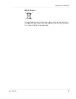
Page 65: ... Dec 16 65 WEEE Notice If you purchased your AirLink RV50 Series devices in Europe please return it to your dealer or supplier at the end of its life WEEE products may be recognized by their wheeled bin label on the product label ...

Page 66: ...AirLink RV50 Series Hardware User Guide 66 4117313 ...

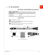
Page 67: ... cable 4 Molex female crimp terminals AWG 20 24 250V 4A Max phosphor bronze tin plated part number 43030 0001 1 Molex male 2x2P Ph 3 0 mm housing 250V 5 A max PA65 black UL94V O part number 43025 0408 1 2 3 4 Power connector end view Power connector housing side view Pin Wire color Open 1 2 3 4 Red Black White Green 3048 mm 10 ft core cable Power connector housing Warning label Male housing Female...

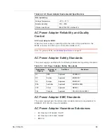
Page 68: ...Note Input voltage range is 90 VAC to 264 VAC Maximum input current is 500 mA at 100 240 VAC Inrush current will not exceed 75 A at 100 240 VAC input and maximum load from a cold start at 25 C Table A 3 AC Power Adapter Output Specifications Minimum Typical Maximum Test conditions Output Voltage 11 4 VDC 12 0 VDC 12 6 VDC 0 1 5 A loading Table A 4 AC Power Adapter Environmental Specifications Oper...

Page 69: ... meets the radiated and conducted emission requirements for EN55022 FCC Part 15 Class B GB9254 AC Power Adapter Hazardous Substances EU Directive 2011 65 EU RoHS EU Directive 2012 19 EU WEEE REACH Non operating Storage Temperature 30 C 70 C Relative Humidity 10 90 Vibration and Shock MIL STD 810D method 514 Table 1 5 AC Power Adapter Safety Standards Regulatory Agency Country or Region Certified S...

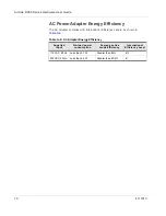
Page 70: ...plies with International Efficiency Levels as shown in Table A 6 Table A 6 AC Adapter Energy Efficiency Supplied Input No load power consumption Average active mode efficiency International Efficiency Level 115 VAC 60 Hz Less than 0 1 W Greater than 85 VI 230 VAC 50 Hz Less than 0 3 W Greater than 80 4 V ...

Page 71: ...conforms with the essential requirements of the applicable EC directives DCE Data Communications Equipment A device that sits between the data terminal equipment DTE and a data transmission circuit Usually the DCE is a modem Diversity Antenna diversity also called space diversity is a scheme that uses two or more antennas to improve the quality and reliability of a wireless link Often especially i...

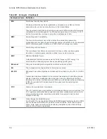
Page 72: ...acting system losses and adding system gains Ethernet Computer networking technologies for local area networks LANs EU The European Union Organization of European countries EV DO Enhanced Voice Data Optimized or Enhanced Voice Data Only Ev DO EV EVDO etc A telecommunications standard for the wireless transmission of data through radio signals typically for broadband Internet access It uses multipl...

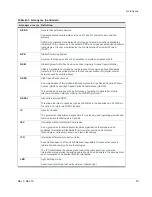
Page 73: ...e of existing 3rd generation mobile telecommunication networks utilizing the WCDMA protocols HSPA Also called evolved HSPA This allows bit rates to reach as high as 168 Mbit s in the downlink and 22 Mbit s in the uplink An improved 3GPP standard IC Industry Canada The government department responsible for overseeing and regulating wireless and communication technologies in Canada IEC International...

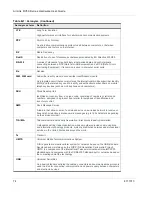
Page 74: ... a product by a retailer for purposes of identification and inventory control SMS Short Message Service A feature that allows users of a wireless device on a wireless network to receive or transmit short electronic alphanumeric messages up to 160 characters depending on the service provider TIA EIA Telecommunications Industry Association Electronics Industry Association A standards setting trade o...

Page 75: ...0 DC voltage transients 29 Description product 11 Digital output 39 Dual SIM 16 E Environmental Testing 20 Ethernet LEDs 42 specification 28 virtual Ethernet port 27 Events Reporting 22 F Features 11 Fusing 29 G Glossary 71 GNSS 21 GPS See GNSS Grounding the chassis 30 H Host Interfaces 20 I I O Configuration 34 Input analog 38 dry contact switch 37 ignition switch 36 Installation connect data cab...

Page 76: ...ing 48 Regulatory information 63 Regulatory specifications 69 Reliability 60 Reset to factory default settings 48 RF specifications 25 S Screw Torque 21 Security 22 Serial connector pin out 28 Serial port 28 virtual serial port 27 SIM cards insert 24 SIM dual 16 Specifications 19 51 environmental 19 environmental testing 20 GNSS 21 Input Output 20 regulatory 69 RF 25 Standards regulatory 69 T Tool...

Page 77: ......

Page 78: ......

Reviews: