background image

AirPrime XA1110 and XM1110

Hardware Design Guide

41111116

Rev 3.0

Summary of Contents for AirPrime XA1110

Page 1: ...AirPrime XA1110 and XM1110 Hardware Design Guide 41111116 Rev 3 0...

Page 2: ...raft the Sierra Wireless modem MUST BE POWERED OFF When operating the Sierra Wireless modem can transmit signals that could interfere with various onboard systems Note Some airlines may permit the use...

Page 3: ...d trademarks of Microsoft Corporation Macintosh and Mac OS X are registered trademarks of Apple Inc registered in the U S and other countries QUALCOMM is a registered trademark of QUALCOMM Incorporate...

Page 4: ...ut Underneath the GNSS Module 17 Keep XA1110 Far Away from High Profile or Metal Canned Components 19 Placement 20 Trace 20 Ground Segmentation 21 Ground Plane for XA1110 21 Thermal Profile for SMD Mo...

Page 5: ...y Time 30 The Delay Time Caused by the Cable 31 Calculating the Delay Time in Respect to the Communication Cable Length 31 Waveform Rising Time Caused by OP amp 32 Recommended OP amp 32 Voltage Degrad...

Page 6: ...t off or weakened Please do not assume the receiver has malfunctioned This document provides the necessary guidelines for a successful system design using GNSS modules For detailed module specificatio...

Page 7: ...Adding a linear regulator LDO is rather than a switched DC DC power supplier in the ripple 3 Using enough decoupling capacitors with the VCC for stable voltage Figure 2 1 Power Design for the GNSS Mod...

Page 8: ...on t connect diode s to RX TX as it will decrease the signal driving capability which might adversely affect the RX TX signal level In some cases no data output will occur 4 If RS232 logic level is ne...

Page 9: ...ramic patch antenna because of its small form factor and low cost There are two types of antennas passive and active A passive antenna is a standalone component without a signal amplifier such as an L...

Page 10: ...nufacturer 5 For 50 matching please refer to 50 Antenna Matching Figure 2 4 PCB Trace Design for Antenna Impedance Matching Selecting an Active Antenna Architecture for the GNSS Module An external act...

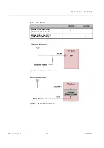
Page 11: ...esign Rev 3 0 Aug 19 11 41111116 Figure 2 5 Mode 1 External Choke Coil Figure 2 6 Mode 2 Internal Choke Coil Table 2 1 Modes XM1110 XA1110 Mode 1 via the VANT External Choke Coil Mode 2 from the VCC I...

Page 12: ...Unictron 1 Pulse Antenna Figure 2 7 Pulse Schematic Design Figure 2 8 Pulse PCB Layout Check antenna datasheet before tuning RF to match the component footprint such as C27 C28 You can base this on PC...

Page 13: ...mal value in order to meet the GNSS s frequency and for good reception Unictron web site http www unictron com index Note The values for C26 C27 C28 C29 and C30 are tuned based on your trace External...

Page 14: ...tion Power Supply 3 3V DC Current 5mA IDC 11mA at 3 3V Total Gain 27 3dB Output VSWR 2 0 Impendence 50 Noise Figure 2dB Table 2 3 Beidou GPS External Antenna Characteristic Specification Polarization...

Page 15: ...a factory default setting Cable Delay Compensation In some cases a long distance connection 300m may be needed For a timing application the cable length is critical For more information on 1PPS signal...

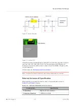
Page 16: ...an boost 1 8V to 3 3V refer to Figure 2 13 below TPS61097A 33 is the TI s boost IC which can support boost functionality In its application C1 and C2 need to use 10uF and L1 is 10uH It can support app...

Page 17: ...process Layout Underneath the GNSS Module In general GNSS modules have high receiving sensitivity at around 165dBm During hardware integration try to avoid noise or harmonics in the following bands to...

Page 18: ...erwise it will cause a sensitivity decrease For XA1110 To avoid the interference place many vias on the two sides of the RF trace which goes from the module to the SMA RF connector on your system PCB...

Page 19: ...ecially those enclosed in metal cases such as the E CAP coin battery and Pin Header The antenna field pattern can be affected and pattern distortion can occur At worst this will decrease the GNSS sign...

Page 20: ...high speed digital processing circuitry in proximity to high current switching power circuitry in proximity to clock sources circuitry Trace 1 The USB differential signals should be traced closely and...

Page 21: ...no crossing of microstrip or current between the two component sets with ground each set is to be contacted to one point only Another method is to place the two different sets at different layers of...

Page 22: ...Hardware Design Guide Rev 3 0 Aug 19 22 41111116 Figure 2 24 Ground Plane for FR4 Design...

Page 23: ...0 C Time above 220 C tp 40 90sec Optimal cooling rate 3 C sec from peak to 220 C The oxygen concentration 2000 ppm Figure 3 1 SMT Reflow Soldering Temperature Profile SMT Solder Mask Using the dimensi...

Page 24: ...hematic design The following is a list of possible items to check Item 1 VCC The voltage should be kept between 3V to 4 3V typical 3 3V Item 2 VBACKUP The voltage should be kept between 2 0V and 4 3V...

Page 25: ...capacitors The service life of a super capacitor is greatly dependent on the operating temperature humidity applied voltage current and backup time Therefore the service life is determined based on t...

Page 26: ...layer to minimize the trace width in a specific PCB such as FR4 and impedance For impedance calculation there is free software available to calculate the trace width or impedance Once such software pa...

Page 27: ...ion Most Sierra Wireless modules use a set of communication ports in TTL logic A bridge IC may be needed for RS232 signal conversion The supported baud rates are 4800 9600 14400 19200 38400 57600 and...

Page 28: ...sen USB Bridge IC is successfully installed onto Windows or another operating system the USB Bridge IC will automatically be recognized as a COM port Note a proper driver must be installed for the USB...

Page 29: ...implemented to prevent waveform distortion Depending on your application an OP amp can be added to control the accuracy of the voltage level for the 1PPS signal When using a 1PPS signal for time synch...

Page 30: ...for amplification pay close attention to the coaxial cable time delay and the rising time of the wave form due to the OP amp s slew rate A brief explanation for this is given below Figure E 2 shows th...

Page 31: ...speed of the traveling waveform 2 The distance of the wave form traveled 3 The delay time Distance of the wave form traveled m Speed of the waveform m s Delay Time ns If the speed of the waveform in t...

Page 32: ...shortened as well Figure E 5 Slew Rate Recommended OP amp If an inadequate OP amp is chosen i e with a low slew rate the delay at the rising time introduced to the waveform can be significantly larger...

Page 33: ...or false welding 3 Special attention is needed for the PCBA board during reflow soldering to see if there are any symptoms of bending or deformation to the PCBA board possibly due to the weight of th...

Page 34: ...sing excess force which may cause a rotational offset to the patch antennas 1 The blade and the patch antenna must have a gap greater than 0 6mm 2 Do not use the patch antenna as the leverage point wh...

Page 35: ...oth conditions may lead to defects such as electrical shortage empty solder and etc 5 Make sure the vacuum mouthpiece is able to bear the weight of the GPS module in order to prevent a positional shif...

Page 36: ...of the solder paste used 3 The steel plate must be properly assessed before and after use so its measurement stays strictly within the specification set by SOP 4 Watch out for the spacing between the...

Reviews: