General Rules for Design
Rev 3.0 Aug.19
17
41111116
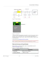
For signal level shift, when your host system is 1.8V and the Sierra Wireless
module is 3.3V, the host system can control the Sierra Wireless module by using
a signal level shift circuit (refer to
below). R1 to R4’s values are
default values. In your design, you can adjust their values to achieve control. The
2N7002L
can select low RDS(On) to reduce power consumption through a
voltage drop.
Figure 2-15: Signal Level Shift Circuit
Layout Guidelines
Please follow the layout guidelines during the design process.
Layout Underneath the GNSS Module
In general, GNSS modules have high receiving sensitivity at around -165dBm.
During hardware integration, try to avoid noise or harmonics in the following
bands to prevent unnecessary reception degradation:
•
Beidou 1561.098MHz ±2.046MHz and GPS 1572.42MHz±2MHz
•
GLONASS 1598.0625~1605.375MHz
Modern GNSS positioning products include many components such as an LCD
screen, MCU, high speed digital signal (access memory card), and an RF system
(i.e. Cellular module, BT, Wi-Fi, DVB-T). Keep these components away from the
GNSS module to avoid noise interference, otherwise it may result in poor GNSS
RF reception.
For XM1110
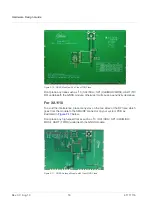
Don’t leave any trace or mark underneath the GNSS module as indicated by the
circled area in figure
below.


