background image

Rev 2.0  Apr.20

22

41113415

6

6: References

Refer to the following documents for more information. Visit

http://source.sierrawireless.com

 for the complete range of available documentation.

1.

AirPrime XS1110 Product Technical Specification
Reference number: 41113354

2.

AirPrime GNSS Tool User Guide
Reference number: 41111068

Summary of Contents for AirPrime XS1110

Page 1: ...AirPrime XS1110 Development Kit User Guide 41113415 Rev 2 0...

Page 2: ...n aircraft the Sierra Wireless product MUST BE POWERED OFF When operating the Sierra Wireless product can transmit signals that could interfere with various onboard systems Note Some airlines may perm...

Page 3: ...ed trademarks of Microsoft Corporation Other trademarks are the property of their respective owners Contact Information Revision History Sales information and technical support including warranty and...

Page 4: ...a Connection 8 SYSTEM0 8 I2C 9 BOOT Mode 10 1PPS INT 11 WAKE UP 12 NRESET 12 Micro B USB 12 Software Usage 14 System Requirements 14 USB Driver and GNSS Tool 14 Installing the USB Driver 15 Using GNSS...

Page 5: ...for users to record all module data such as satellites status time to first fix TTFF date and time Note that The GNSS signal may be cut off or become seriously weakened if you operate the Development...

Page 6: ...llowing figure identifies the location of the Development Kit s connectors and other components Figure 2 1 Development Kit Connectors and Components Refer to the subsequent chapter Interfaces on page...

Page 7: ...evelopment Kit Module The Development Kit includes an XS1110 module Figure 3 1 XS1110 on the Development Kit Note that the XS1110 requires an external RF antenna to be connected to the RF SMA connecto...

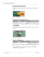
Page 8: ...smissions are done via UART or I2C Figure 3 3 SYSTEM0 Header To set transmission selection to UART disconnect jumper on SYSTEM0 for SYSTEM0 pins to pull high default Table 3 2 Antenna Connector Detail...

Page 9: ...er pull low status The Development Kit must then be re powered by unplugging then replugging the power supply after which the NRESET button must be pressed to reboot the module to change transmission...

Page 10: ...de header is used to place the module in Flash download mode to perform firmware updates Figure 3 7 BOOT Mode Header Table 3 4 I2C Header Details Component PCB Label Description 5 pin header P1 I2C si...

Page 11: ...d INT for I2C header Figure 3 8 1PPS INT Header Table 3 7 1PPS INT Details Component PCB Label Description 5 pin header P2 1PPS INT header Table 3 8 1PPS INT Header Pins Pin Number Pin Name Descriptio...

Page 12: ...ost device and interfaces to an on board CP2102N IC which provides access to the module s UART interface When the Development Kit is powered ON LED1 Power is lit the host device can connect to the XS1...

Page 13: ...ing of 115200kbps baud rate and update rate of 1Hz Figure 3 11 Micro B USB Connector and Power LED Table 3 11 Micro B USB Connector Details Component PCB Label Description Micro B USB connector JP1 Co...

Page 14: ...river and GNSS Tool Before setting up the connection between the module s UART port and the PC you will need the Development Kit USB Driver CP210x VCP and GNSS Tool exe to operate the Development Kit...

Page 15: ...1 Driver Installation Folder 2 Click Install Figure 4 2 Starting the Installation Process 3 After the installation is complete you may need to restart your computer Please follow the instructions on...

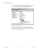
Page 16: ...ge COM is present If so the Development Kit is set up and ready for use Figure 4 4 Accessing the Port Properties COM9 represents the virtual COM port number generated for the USB connection to the Dev...

Page 17: ...u item will display the Command window 2 NMEA List clicking on this menu item will display a window with NMEA infor mation 3 CNR Signal clicking on this menu item will display the CNR signal window 4...

Page 18: ...20 18 41113415 After the Development Kit is connected with the PC please choose the correct COM Port and Baud Rate Figure 4 6 COM Port Dialog If you want more information about the GNSS Tool software...

Page 19: ...usly No NMEA data or GNSS signals 1 USB was not set up properly 2 COM port or baud rate value is incorrect 1 Check to see if the USB connector to the PC or Development Kit is connected properly 2 Doub...

Page 20: ...possible to have weak GNSS signal in the following situations Table 5 2 Examples Where Poor GNSS Signals May Occur Inside a tunnel where the GNSS signal is blocked Underneath infrastructure e g a bri...

Page 21: ...result in no GNSS reception GPS satellites are the property of the United States Army Sometimes they will tune down accuracy for unknown reasons In such cases the GPS position may not be accurate Next...

Page 22: ...lowing documents for more information Visit http source sierrawireless com for the complete range of available documentation 1 AirPrime XS1110 Product Technical Specification Reference number 41113354...

Reviews: