© 2015 Sierra Wireless. All rights reserved.
13811 Wireless Way
Main +1 604 231 1100
Richmond, BC
Fax +1 604 231 1109
2400432, Rev. 1
Canada, V6V 3A4
www.sierrawireless.com
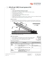
MiniCard (MC) Development Kit
Kit Contents
•
(1) MC-series development kit printed circuit assembly
•
(2) Ultra-wideband 4G dipole swivel terminal antennas
•
(6) RF cables—U.FL micro coaxial cables (3 for Main/AUX/GNSS, 3 spares)
•
(1) U.FL connector push/pull tool
•
(1) USB cable (Type A to micro-B 3.0)
•
(1) AC wall adapter power supply and international plug kit
•
(1) micro-SIM to SIM adapter
•
(2) Thermal pads (1 to install on heat shield, 1 spare). Pad type: 30.5 x 44.0 mm TENNVAC GP5000
•
(3) M2x3 Phillips head module screws (2 to install module, 1 spare)
Module Insertion
1.
Remove backing from the thermal pad (both sides), and position the thermal pad on the heat sink.
2.
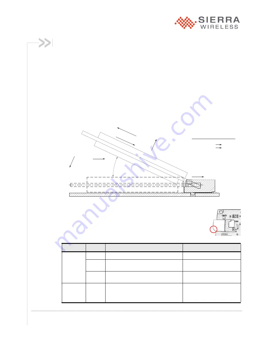
Insert the module as shown. (Insert at a 31º angle, rotate down, and push fully into the connector.)
3.
Secure the module with two M2 screws.
SIM Card Connection
1.
Slide the SIM card into CN202 (top left corner of the PCB), noting the location
of the notched corner. (If ESIM is enabled, DO NOT use a SIM in CN202.)
2.
If supporting dual SIMs, insert a second SIM card into CN206.
Power Source Selection
Connector
Jump
Description
Power connector(s) to use
CN101
(PWR IN
SELECT)
Pins 1 & 2
Power provided by barrel jack (AC adapter)
CN103
Pins 3 & 4
Power provided by banana jack (3.125–4.4VDC)
Disable on-board LDO
CN114 (VCC) & CN116, or
CN115 (VCC_MODULE) & CN116
Pins 5 & 6
Power provided by USB cable (Default jumper
location)
CN105
CN117
CONNECT
MAIN VCC
Pins 1 & 2
Jumper required when selected power type is
AC adapter or USB cable.
Remove the jumper to isolate module power
from other circuits on the board.
HOW TO MATE (INSTALL) AND EXTRACT
MATE:
ß
â
ã
ä
â
MATE
EXTRACT:
ß
LEAD-IN
ã
RISE UP
ä
EXTRACT
á
PUSH
à
ROTATE
31°


