attempt to read/write the
tdata1-3
registers in machine mode when
dmode
=1 raises an illegal
instruction exception.
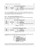
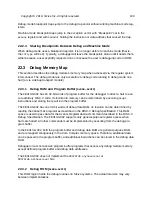
Debug Control and Status Register (
This register gives information about debug capabilities and status. Its detailed functionality is
described in
The RISC‑V Debug Specification 0.13
.
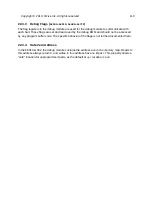
When entering debug mode, the current PC is copied here. When leaving debug mode, execu-
tion resumes at this PC.
This register is generally reserved for use by Debug ROM in order to save registers needed by
the code in Debug ROM. The debugger may use it as described in
The RISC‑V Debug Specifi-
cation 0.13
.
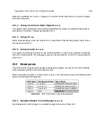
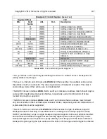
The FE310-G002 supports eight hardware breakpoint registers per hart, which can be flexibly
shared between debug mode and machine mode.
When a breakpoint register is selected with
tselect
, the other CSRs access the following infor-
mation for the selected breakpoint:
CSR Name
Breakpoint Alias
Description
tselect
tselect
Breakpoint selection index
tdata1
mcontrol
Breakpoint match control
tdata2
maddress
Breakpoint match address
tdata3
N/A
Reserved
Table 104:
TDR CSRs when used as Breakpoints
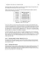
Breakpoint Match Control Register
Each breakpoint control register is a read/write register laid out in Table 105.
Copyright © 2019, SiFive Inc. All rights reserved.
106
Summary of Contents for FE310-G002
Page 1: ...SiFive FE310 G002 Manual v19p05 SiFive Inc ...
Page 11: ...Figure 1 FE310 G002 top level block diagram Copyright 2019 SiFive Inc All rights reserved 9 ...
Page 15: ...Chapter 2 List of Abbreviations and Terms 13 ...
Page 23: ...Chapter 4 Memory Map The memory map of the FE310 G002 is shown in Table 4 21 ...

