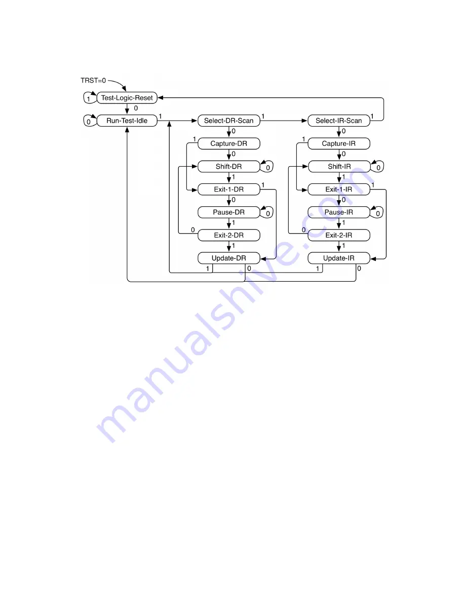
Figure 13:
JTAG TAPC state machine.
The JTAG logic must be asynchronously reset by asserting the power-on-reset signal. This dri-
ves an internal
jtag_reset
signal.
Asserting
jtag_reset
resets both the JTAG DTM and debug module test logic. Because parts
of the debug logic require synchronous reset, the
jtag_reset
signal is synchronized inside the
FE310-G002.
During operation, the JTAG DTM logic can also be reset without
jtag_reset
by issuing 5
jtag_TCK
clock ticks with
jtag_TMS
asserted. This action resets only the JTAG DTM, not the
debug module.
The JTAG logic always operates in its own clock domain clocked by
jtag_TCK
. The JTAG logic
is fully static and has no minimum clock frequency. The maximum
jtag_TCK
frequency is part-
specific.
Copyright © 2019, SiFive Inc. All rights reserved.
112
Summary of Contents for FE310-G002
Page 1: ...SiFive FE310 G002 Manual v19p05 SiFive Inc ...
Page 11: ...Figure 1 FE310 G002 top level block diagram Copyright 2019 SiFive Inc All rights reserved 9 ...
Page 15: ...Chapter 2 List of Abbreviations and Terms 13 ...
Page 23: ...Chapter 4 Memory Map The memory map of the FE310 G002 is shown in Table 4 21 ...


