This chapter describes the operation of SiFive debug hardware, which follows
The RISC‑V
Debug Specification 0.13
. Currently only interactive debug and hardware breakpoints are sup-
ported.
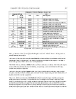
This section describes the per-hart trace and debug registers (TDRs), which are mapped into
the CSR space as follows:
CSR Name
Description
Allowed Access Modes
tselect
Trace and debug register select
D, M
tdata1
First field of selected TDR
D, M
tdata2
Second field of selected TDR
D, M
tdata3
Third field of selected TDR
D, M
dcsr
Debug control and status register
D
dpc
Debug PC
D
dscratch
Debug scratch register
D
Table 99:
Debug Control and Status Registers
The
dcsr
,
dpc
, and
dscratch
registers are only accessible in debug mode, while the
tselect
and
tdata1-3
registers are accessible from either debug mode or machine mode.
Trace and Debug Register Select (
To support a large and variable number of TDRs for tracing and breakpoints, they are accessed
through one level of indirection where the
tselect
register selects which bank of three
tdata1-3
registers are accessed via the other three addresses.
The
tselect
register has the format shown below:
104
Summary of Contents for FE310-G002
Page 1: ...SiFive FE310 G002 Manual v19p05 SiFive Inc ...
Page 11: ...Figure 1 FE310 G002 top level block diagram Copyright 2019 SiFive Inc All rights reserved 9 ...
Page 15: ...Chapter 2 List of Abbreviations and Terms 13 ...
Page 23: ...Chapter 4 Memory Map The memory map of the FE310 G002 is shown in Table 4 21 ...

