TSX1D200MTS V1 FEB13
- 32 -
Check points
& maintenance
items
Fault
N
o
a
rc
N
o
g
a
s
N
o
w
ir
e
fe
e
d
B
a
d
a
rc
s
ta
rt
U
n
s
ta
b
le
a
rc
W
e
ld
s
e
a
m
e
d
g
e
u
n
c
le
a
n
W
ir
e
s
tic
k
in
g
to
m
e
ta
l
C
o
n
d
u
c
tiv
e
c
o
n
ta
c
t t
ip
W
e
ld
P
o
ro
s
ity
•
Loose connection
•
Gas Hose
•
Damaged gas tube
•
•
Correct size feed roll &
guide tube for wire diameter
•
•
•
•
•
Clean groove in drive roll
•
•
•
•
Wire Feeder
•
Pressure is not too tight,
and guide tube is clear of
shavings
•
•
•
•
•
The cable is not over bent
•
•
Welding Gun
& Cable
•
Torch consumables are not
damaged, and are correct
for the application
•
•
Contact tip, nozzle and
nozzle joint are secure
•
•
Welding Gun
•
Torch fitting is not too tight
or loose
•
•
•
Cables are not broken
•
•
•
•
•
Gun Power Cable
& Switch Control
Cable
•
Cables are not damaged
•
•
•
Clean from oil, dirt, rust and
paint
•
•
•
Material surface
& wire length
•
Wire does not need cutting
back
•
•
•
•
Good earth connection
•
•
•
•
Output Cables
•
Cable connections are tight
•
•
•
•
Ensure the cross-sectional
area of the cable is
sufficient for current
required
•
•
•
•
Welding Cable
•
Cable is not coiled
Welding
Conditions
•
Check parameters, torch
geometry, welding speed
and stick out
•
•
•
•
•
Summary of Contents for MTS 200
Page 1: ...MTS 200 User Manual SWMTS001 TSX1D200MTS ...
Page 9: ...TSX1D200MTS V1 FEB13 9 Diagram for Installation for MIG Applications ...
Page 12: ...TSX1D200MTS V1 FEB13 12 Diagram for Installation for Spool On Gun MIG Applications ...
Page 14: ...TSX1D200MTS V1 FEB13 14 Diagram for Installation for TIG Applications ...
Page 16: ...TSX1D200MTS V1 FEB13 16 Diagram for Installation for MMA Applications ...
Page 22: ...TSX1D200MTS V1 FEB13 22 4 Hot Start ...
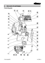
Page 27: ...TSX1D200MTS V1 FEB13 27 8 Parts List Circuit Diagram Parts Diagram ...


