3
COVERING MATERIAL:
Your 3D MAYHEM ARF has been professionally covered with
premium Oracover
®
polyester film covering. The Oracover
®
colors
are #10 White, #23 Red, #52 Blue, and #71 Black. (Note: In the
United States, Oracover
®
is sold under the name of Hangar 9
Ultracoat
®
. The equivalent Ultracoat
®
colors are called #870 White,
#866 True Red, #885 Midnight Blue, and #874 Black).
You may notice that some wrinkles might develop in the covering
after removing the parts from their plastic bags. If that is the case,
there is no need to be alarmed. This is perfectly normal in low
humidity climates. Your model was built and covered in a part of
the world with relatively high humidity and therefore the wood was
likely carrying a fair amount of moisture. When exposed to drier air,
the wood typically loses this moisture, dimensionally "shrinking"
slightly in the process. In turn, this causes the wrinkles.
Any wrinkles that appear in the covering are easy to remove by
using a hobby-type heat iron.
We suggest covering the iron's
shoe with a thin cotton cloth, such as an old T-shirt, to prevent
scratching the film. The iron should be set to about 280
O
- 300
O
F.
First, use the heated iron to go over all the seams and color joints
in the covering, making they are all sealed down and well adhered.
Then use the heated iron to lightly shrink the material - do not
press on it. Once the covering is tight, lightly iron the material back
down to the wood. You can also use a hobby-type heat gun to
re-shrink the covering, but you must be extra careful around the
seams. Re-heating seams may cause them to "creep", making
them unsightly.
MODELER’S TIP: One of the most common problems associated
with shrinking any covering film is controlling the heat around
seams. Heat applied close to or directly onto seams reheats the
covering adhesive and the seam will often "crawl". This is easy to
control. Just tear a few paper towels into strips and soak them in
cool tap water. Lay the wet strips over any covering seam and use
your heat gun or iron as you normally would. The wet strips keep
the seam cool while the covering immediately next to it shrinks.
WARPS!
Light weight is a key ingrediant in the 3D MAYHEM’S flight profile.
Because of their light weight construction, the ailerons, elevators,
and rudder of the MAYHEM can become warped whenever the
covering material is heated for shrinking. Care must be used to
make sure that the control surfaces remain straight as the covering
cools. Avoid putting a twist in the part while taking out wrinkles.
If you find a warp in one of your parts, the warp can almost always
be removed by twisting the surface in the opposite direction and
holding it there while heat is applied to the covering material. After
the covering cools, release the control surface and recheck for the
warp. The amount of reverse twist and heat that you apply, will
determine where the control surface ends up after it cools.
Note: When trying to remove a warp, an extra set of hands are
needed. Have someone assist you. While one person holds the
reverse twist in the control surface, the other person applies the
heat by passing a covering iron over both sides of the part.
WING ASSEMBLY - OVERVIEW:
The wing of the MAYHEM comes in two pieces, a right wing panel
and a left wing panel, which will be permanently glued together to
make a strong one-piece wing.
For precise control of the ailerons, there is one aileron servo
mounted in each wing panel.
As received in the kit, the wing panels have the ailerons in place
but not yet permanently hinged. Hinging the ailerons will be done
later. For now, remove the ailerons from the wing panels and pull
out all the CA hinges and set them aside until called for.
To avoid unnecessary dents, dings, or scuffing of the airplane
parts, we suggest that you cover your workbench with a soft
household blanket or foam sheet while assemblying your model.
WING ASSEMBLY, PART I: Installing the aileron servos
For the following steps you will need these parts:
•
1 - Right Wing Panel
•
1 - Left Wing Panel
•
2 - Aileron Servos (not supplied)
•
2 - 6” or 12” Servo Extension Chords (not supplied)
[actual length you need depends upon the length of the
pigtail wires on your particular servo. For the Hitec
®
servos
shown in the pictures, we used 6” extension chords.]
•
1 - Servo Y-Harness Chord (not supplied)
❑
1) Before installing the aileron servos in the wing, you must
attach a servo extension chord onto the end of the aileron servo
wire. The combined length required is approximately 21”. A 6” or
12” extension chord will usually provide sufficient length. Plug the
extension chord onto the servo wire and secure well with tape.
Also, install the mounting grommets and eyelets onto the servo as
described in the instructions that came with your servos.
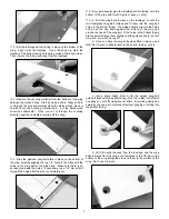
❑
2) Inside the aileron servo bay opening, you will find a short
length of wood with a string tied to it. The string will be used to pull
the aileron servo wire through the wing panel to the center of the
wing. Gently break the wood piece loose from the wing structure,
and pull it and the string a few inches out of the servo bay
opening. Remove the wood from the string and disgard it. Tie the
end of the string securely to the end of the servo wire, as shown.
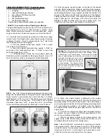
❑
3) On the top of each wing panel, just inboard of the center
wing rib, you will find another opening. This is the exit hole for the
aileron servo wire. Inside this opening you will see another piece
of wood with a string tied to it. This is the other end of the string in
the aileron servo bay. Break the wood piece loose and carefully
pull the string and servo wire through the wing until the servo wire
emerges from the opening in the top of the wing.
Note: You may occasionally feel like the wire has become stuck
inside the wing. This is simply the plug on the end of the servo wire


