background image

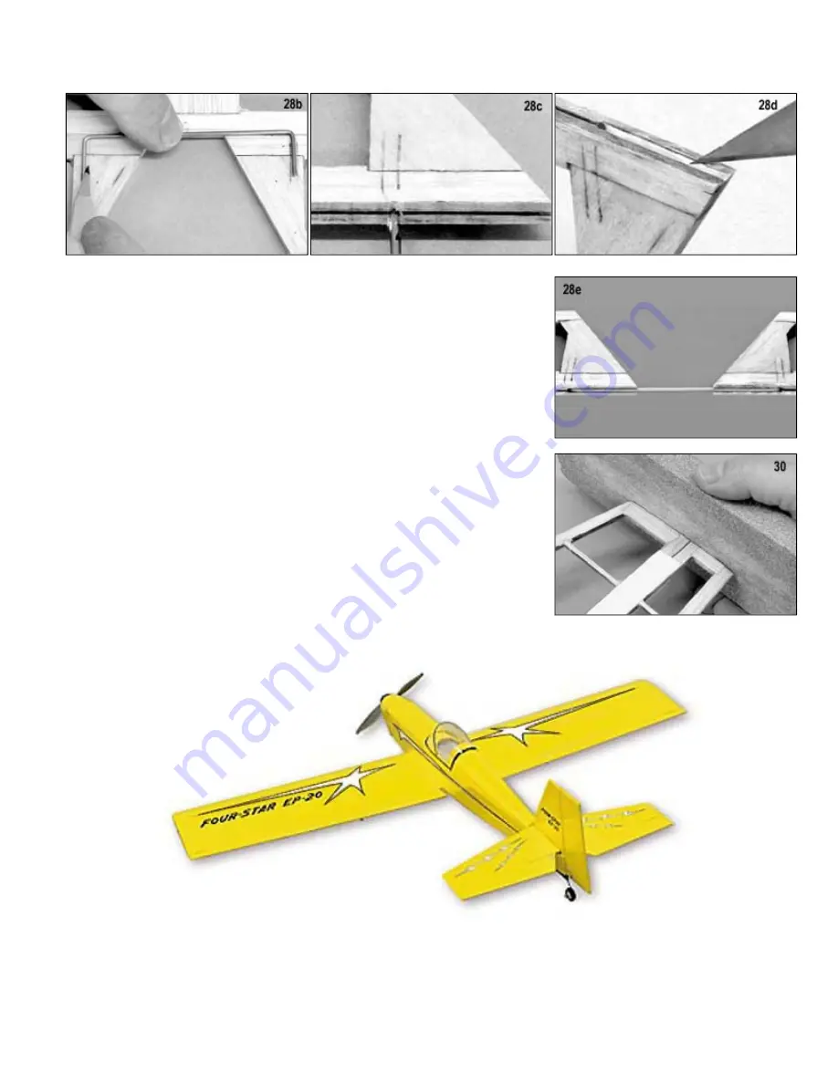
d. Use a sharp #11 hobby knife to cut a groove in the leading edge to accept the Wire Joiner.


e.

 
Wipe the Wire Joiner clean with some type of solvent (paint thinner, mineral 
spirits, rubbing alcohol, etc.), and then glue it into the elevators with epoxy. Be 
sure to keep the leading edges of the two elevators aligned straight while the glue 
dries.


f.

 
Use a sanding block to bevel the leading edge of the elevators to a "v" shape, 
using the hinge line as a guide. Refer to the cross-section drawing of the elevator 
on the plan.

 
29.

 
Assemble all the fin and rudder parts over the plan. When dry, remove them from 
the plan and sand them to final shape. Fin - round the leading edge, leave the 
trailing edge square. Rudder - round the trailing edge, "v" shape the leading edge.

 
30.

 
Temporarily tape the elevators to the back of the stabilizer. Then use a sanding 
block to sand the ends of both pieces together until they match perfectly. The tips 
can be left square or sanded round if you prefer.

 
The tail surfaces are now complete and can be set aside until covering. They will 
be hinged after covering is done.


Summary of Contents for Four-Star 20EP

Page 1: ...odel you ll want to take to the flying field every time The FOUR STAR 20EP is the first Four Star kit designed primarily for electric power although the structure is configured to easily accommodate a glow engine if you wish to go that way This use of a modern electric power system in the legendary Four Star has produced a marvelous little R C ship that is a pure joy to fly It s small enough to ca...

Page 2: ...r flight tests we have used the Hitec Electron 6 weight 19 grams and the FMA M5 weight 11 grams Both are dual conversion receivers SERVOS standard size servos the ones that come with most sport radio systems are too big and too heavy for the Four Star 20EP You will need smaller servos In our prototypes airplanes we used Hitec HS 81 Micro Servos which have a torque rating of 36 oz in and weigh 58 o...

Page 3: ...ist of changes if using a glow engine is short 1 Leave the 3 small circles near the bottom of the F 1A and F 1B plywood formers in place Do not punch them out Work some glue into the cut lines to keep them permanently in place The purpose of those 3 holes was to cool the electric motor battery Obviously not needed in a glow version In fact they need to be sealed up so that glow fuel exhaust residu...

Page 4: ...rs Balsa Wood Sticks 3 3 32 x3 16 x36 Stringers 1 1 16 x1 4 x18 Capstrips 8 1 8 x1 8 x24 Sub Spars 4 1 8 x3 8 x36 Main Spars Main Spar Doublers Servo Bay 4 1 4 x1 4 x24 Leading Trailing Edges Balsa Wood Sheets 2 1 16 x1 1 4 x24 Trailing Edge Top Sheet 2 1 16 x1 1 2 x24 Trailing Edge Bottom Sheet 2 1 16 x2 x24 Wing Center Section Sheeting 1 3 32 x3 x13 Fuselage Top Sheeting Hardwood 2 1 4 x1 4 x2 9...

Page 5: ... ...

Page 6: ... have 2 W 1 ribs 2 W 1A 2 W 2 2 W 3 12 W 4 2 W 4A and 2 Wingtips b Glue W 1A to the front of each W 1 rib being very careful to get the edges exactly aligned Be sure to make a right and left W 1 rib assembly 3a Carefully remove one of the Spar Webs from laser cut sheet no 4 Hold the Spar Web against the plan and familiarize yourself with it s exact orientation Note that the open rib notches should...

Page 7: ...sa Leading Edge in place 10 Glue two 1 8 x1 8 x24 Balsa Sub Spars in place in the top rib notches 11a 1 16 x2 x24 balsa is provided for sheeting the center section of the wing Start by cutting the stock into seven 3 1 4 long pieces b Glue one of the 3 1 4 long pieces in place up against the trailing edge top sheet Trim the width of another 3 1 4 long piece of sheeting stock to fit between the firs...

Page 8: ...t are cut into the W 1 end ribs to indicate the location for the laser cut plywood DB Dihedral Brace Use a sharp 11 hobby knife to cut through the rib between the dashes to create an opening for the Dihedral Brace Do the same for both the W 1 end ribs of BOTH wing panels 19a Trial fit both wing panels together with the Dihedral Brace installed Make sure the panels come together tightly with no gap...

Page 9: ... them to the back of the wing after all the parts are covered TAIL SURFACES Begin by taping or pinning the Stabilizer and Elevator plan to your building board Cover the plan with a layer of waxed paper to keep glue from sticking to the plan 25a Assemble stabilizer parts S 1 S 2 S 3 S 4 S 5 and S 9 together over the plan Glue the parts together where they join b Add the stabilizer ribs S 6 S 7 and ...

Page 10: ... as a guide Refer to the cross section drawing of the elevator on the plan 29 Assemble all the fin and rudder parts over the plan When dry remove them from the plan and sand them to final shape Fin round the leading edge leave the trailing edge square Rudder round the trailing edge v shape the leading edge 30 Temporarily tape the elevators to the back of the stabilizer Then use a sanding block to ...

Page 11: ... Double check to make sure you are gluing into the P 1 side which is the longer piece see CROSS SECTION AT F 3 drawing on the plan Glue in place with epoxy glue Be careful not to get any glue in the threads 34a Remove the balsa Fuselage Top from laser cut sheet no 2 Notice the series of dashed lines cutting across the Fuselage Top in the location where top former T 2 will eventually go near the fr...

Page 12: ...ny glue in the threads of the blind nuts c Glue the LG 1 LG 2 assembly in place in the fuselage 42 Glue plywood part BT Battery Tray in place It rests on the edges of the fuselage doublers and up against the front of former F 2 43 Fit the plywood F 1A F 1B firewall assembly in place in the fuselage Note that F 1B is the side of the firewall with two notches to accept the ends of the fuselage top s...

Page 13: ...iameter and shape is not critical an empty yogurt container is about the right size b Trial fit the balsa sheet over the top of formers F 1 T 1 and T 2 Dampen the outside or top of the sheet to help bend over the top formers When ready glue the sheet in place to the formers top stringer and fuselage sides Use tape and or pins to hold the sheet in place until the glue dries c When glue is dry sand ...

Page 14: ... workmanship Fill any small surface gaps with a light weight filler or spackling putty Sand the entire model with 220 grit sandpaper and then again with 360 or 400 grit Covering The Wing Begin the wing by covering the wingtips with seperate pieces of covering material Trim the covering material about 1 8 larger than the wingtips Work the extra 1 8 around and seal down onto the top and bottom surfa...

Page 15: ...ur decals now before the model is completely assembled It s easier to do now while the parts are easy to handle The decals supplied with the Four Star 20EP are sticky back Mylar stickers with a very aggressive adhesive They are NOT water slide decals Also these decals are not die cut and must be cut from the sheet with a sharp 11 hobby knife or scissors A straight edge makes this easier when strai...

Page 16: ... wear a leather glove on the hand that is holding the model part while you are cutting the slots c After all the slots have been cut insert a single hinge halfway into each hinge slot in the stabilizer If the hinge is difficult to push in re insert the knife and move it back and forth in the slot a few more times and then try again DO NOT GLUE THE HINGES IN AT THIS TIME d Now carefully slide the e...

Page 17: ... wing to the trailing edge of stabilizer Both measurements should be the same If there is any difference rotate the stabilizer until the measurements are identical c Also check the alignment of the stabilizer to the wing in the front view The stabilizer should be level with the wing If it is not alter the stab mount platform of the fuselage as needed d When satisfied with the alignment use a fine ...

Page 18: ...r tightening the nuts double check that the wheel still turns freely d Repeat steps a b and c to install the other wheel on the other 6 32 axle bolt 62 Insert the axle bolt into the hole at the bottom of one of the legs of the Aluminum Landing Gear Thread a 6 32 Lock Nut onto the axle bolt and tighten securely Repeat to install the other wheel on the other landing gear leg 63 Mount the main landin...

Page 19: ...ck the exact location on the plan Elevator Pushrod 67 A piece of 1 32 dia x24 long straight music wire is provided for the elevator pushrod a Bend the last 3 8 of one end of the pushrod wire all the way back against itself Mash the bend flat against the pushrod b Push the mashed end inside the open end of a Threaded Coupler If you can t get it in you haven t mashed the wire flat enough yet The wir...

Page 20: ... make a suitable support Hold the balsa support against the front of former F 3 and up against the bottom of the pushrod tubes Mark the positions of both tubes on the support Take the support back out and make a small notch in the support for each tube Then put the support back in position and glue it to the back of F 3 Also glue the pushrod tubes securely in the notches 71 Install your aileron se...

Page 21: ... of the fuselage and extend it back to tail end of the fuselage We drilled a small hole through the fuselage bottom just behind the trailing edge of the wing and pushed the antenna through the hole To hold the antenna at the rear of the fuselage tie a small rubber band on the end of the antenna and then loop the rubber band over the tailwheel wire to keep the antenna taught Motor Installation This...

Page 22: ...fore turning on the airborne on off switch Under no circumstances should you hold this model by the nose when the battery is plugged in or the radio system is turned on Never plug in your flight battery until you are on the flight line ready to fly 81 Open up the front of the Cowling A Dremel tool works great for this If you don t have one another good method is to first drill a series of 1 4 dia ...

Page 23: ... running cool System Tests 85 The completed radio and motor systems can now be powered up and tested for proper operation a Make sure your transmitter aileron elevator and rudder trim levers are in neutral position and that the throttle stick is in the full low throttle position Then turn on your transmitter b Install a charged battery pack inside the fuselage Making very sure of the correct polar...

Page 24: ... their trailing edges Balance Your Airplane Important An R C model should always be balanced with everything on board ready for flight The flight battery must be installed in the fuselage and the propeller and spinner must be mounted in place when balancing the model RECOMMENDED BALANCE POINT 2 3 8 26 to 2 3 4 30 Behind The Leading Edge Of The Wing The main wing spar of the Four Star 20EP is locat...

Page 25: ...e a very experienced pilot Caution Never land your airplane in tall grass or weeds with the electric motor running Always throttle back completely if you land in such terrain or if you nose over after landing Tall grass or a nose over will stall the motor if it is running A stalled motor can overheat the ESC and batteries causing them to fail Join The Club Although the Four Star 20 is small and ca...

Page 26: ...R S HOTLINE for technical support 1 641 623 0215 SIG WEB SITE www sigmfg com Copyright SIG Mfg Co Inc SIG MFG CO INC Montezuma Iowa 50171 0520 LIMIT OF LIABILITY The craftsmanship attention to detail and actions of the builder flyer of this model airplane kit will ultimately determine the airworthiness flight performance and safety of the finished model SIG MFG CO s obligation shall be to replace ...

Reviews: