.
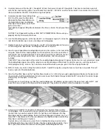
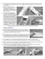
69. Use a long blade on a modeling knife to cut off the excess rudder pushrod tube (from Step 67) and the pull-pull exit tubes
(from Step 68). Cut the tubes as close as you can to the fuselage. Then block sand the tubes, and any excess glue, flush
with the fuselage.
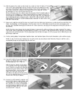
70.
Glue the 10" long piece of 1/8" o.d.
Small Nylon Pushrod Tubing (left over
from Step 68) into the hole in the
Firewall for the Throttle Pushrod. Leave
about 2 inches of the tubing extending in
front of the firewall.
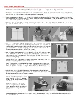
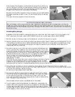
71.
The fuselage is now ready for final
sanding. Use a sanding block with 80
grit paper to sand smooth all the exterior
glue joints on the sides, top and bottom
of the fuselage. Sand all protrusions until
they are level with the surface. Block
sand the exterior corners of the fuselage
slightly round for a more pleasing shape.
The cross sections on Plan Sheet 1 can
be used as reference for shape. Do not
round the corners in the areas where the
wing and stabilizer will be mounted or in
the Hatch area. After leveling everything
with the 80 grit sanding block, go over
the entire fuselage with hand held 220
grit sandpaper.
The basic fuselage construction is now complete! Set the fuselage aside until covering.
Stabilizer And Elevator
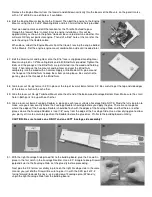
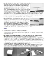
72.
Tape the Stabilizer Plan to the building board, and cover with wax paper. Pin
down over the plan and glue in place all of the 5/16" laser-cut balsa stabilizer parts
S-1, S-2, S-3, S-4, S-5, and S-6. Cut four 5/16" sq. balsa ribs from the 30" long
piece provided, and glue them in place with THIN CA.
73.
Once the glue is dry, remove the Stabilizer frame from the plan and re-glue all the
joints with Medium CA. Use just enough glue to completely fill the joint, plus leave
small fillet of glue between the parts. Take your time and don’t miss any joints!
Each and every one of them contributes to the finished strength of the Stabilizer.
74.
Lay the Stabilizer flat on the building board and lightly block sand both sides to smooth out all the glue joints.
CAUTION: Do not sand so much that you thin down the Stabilizer more than 1/32" under its original 5/16" thickness.
75.
Mark a center-line on the front of the Stabilizer Leading Edge. Using the center-line as a guide, carve and sand the Leading
Edge round. NOTE: Leave the trailing edge and ends of the Stabilizer flat and square.
76.
Temporarily tape the pre-shaped Elevator to the back of the Stabilizer. Use a sanding block to even up the tips of the
Elevator and Stabilizer.
Set the Stabilizer and Elevator aside until time to cover.


