.
128. Anchor the loose end of the antenna on the outside of the model near the rear of
the fuselage using a small rubber band and a T-Pin (an "antenna hook" is also
handy if one came with your radio). Stick the T-Pin into the bottom of the fuselage
at an angle, as shown. Put a drop or two of Slow CA glue on the pin to keep it in
place. Tie the rubber band to the antenna (or the antenna hook) and then loop it
over the T-Pin. The antenna should be just taut, not tight! The rubber band allows
a certain amount of give in case the antenna is snagged by accident.
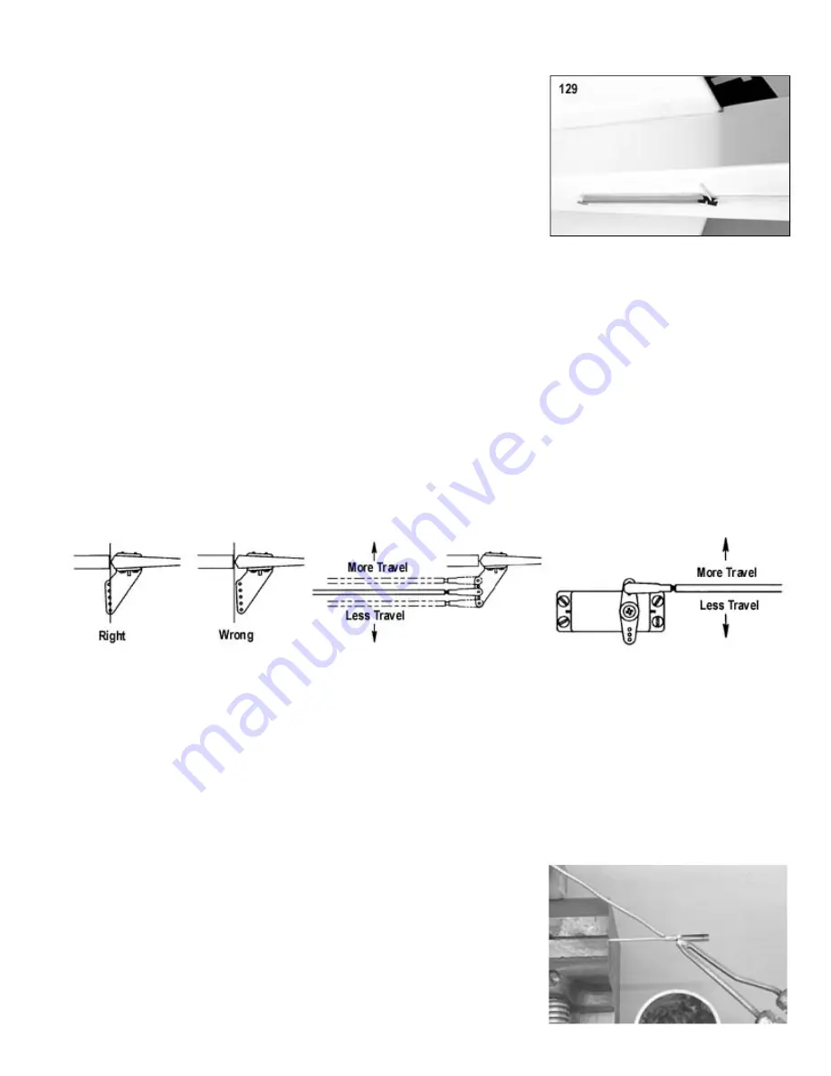
129.
Cut an opening in the left side of the fuselage (the side away from the exhaust) to
accommodate the radio’s on/off switch. Use the switch cover plate as a guide to
mark the location and size of the opening and the two holes for the mounting
screws. Install switch.
CAUTION: Make sure the opening you cut for the switch’s on/off lever is just slightly bigger than the lever, so that the
switch will operate safely, without catching or binding on the wood.
Control Horn Basics
Sometimes the holes in molded plastic control horns and servo arms end up being a little undersize, making it very
hard to install the R/C Links and Pushrod Connectors that attach to them. All of the R/C Links and Pushrod
Connectors in this kit have a pin size of 1/16" dia. If you have difficulty getting the pins to go into the holes in the
control horns or servo arms, open up the holes with a 1/16" dia. drill bit. DO NOT USE A BIT LARGER THAN 1/16"
DIAMETER!
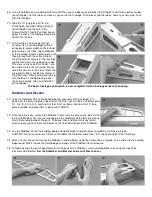
Nylon control horns should always be mounted so that the adjustment holes in the control arm line up with the hinge
line of the control surfaces! If not, the control surface will have unequal travel in one direction.
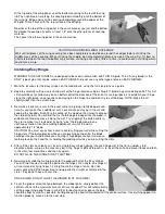
Some radios have a feature called "End Point Adjustment" (sometimes called "Adjustable Travel Volume") that
allows the user to electronically adjust the total travel of the servos, and thus, the total travel of the control surfaces.
This is a very handy feature! If you do not have this radio feature, you can still make control surface travel
adjustments by mechanical means. Move the linkages in the directions shown to get more or less travel.
Why Solder Links
You may be wondering why we provided R/C Solder Links for the servo ends of the aileron, elevator, and rudder pushrods,
when all the rest of the control system installation is solderless! Why didn t we use more Pushrod Connectors, or maybe
just a Z bend in the wire?
Well first off, Z bends are a good alternative, but we felt that they are too difficult for a beginner to make correctly on his
first try. Second, Pushrod Connectors are great, but not in all situations. They are more than adequate for non-
aerodynamic controls like the throttle and nose gear. However the set screw in a Pushrod Connector can come loose! If
that happens to the throttle or nose gear, it most likely won t cause any serious problem. But if it happens to the ailerons,
elevator, or rudder, the airplane will most likely crash! That s why you don t see any Pushrod Connectors on the ailerons,
elevator, or rudder pushrods of the KADET LT-40!
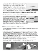
If you have never soldered before, don t worry, it s not difficult. The hardest part
will probably be coming up with a soldering iron (or gun). If you don t want to
purchase one at this time, seek the assistance of someone who already has one
and knows how to use it. The secret to easy soldering is to use plenty of heat!
You need a heavy-duty soldering iron to do this job, not one of the little pencil
style irons that are only intended for soldering small electrical wires and
components. It will take a soldering iron of at least 75 watts (100w or 200w is
better) to solder the R/C Solder Links and pushrod wires in this kit. Use ROSIN
CORE SOLDER (60% tin, 40% lead) and a good brand of SOLDERING PASTE
FLUX. Put the wire in a vise. Coat the end of the wire with soldering paste flux.


