6
❑
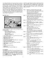
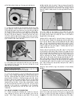
2) Prepare the rudder and elevator servos for mounting by first
inserting the rubber grommets and brass eyelets provided with
your radio system. Place both servos into the servo tray in the
fuselage and use a sharp pencil to mark the mounting screw
locations for both servos onto the servo tray. Remove the servos
and use a 1/16" drill bit to drill pilot holes for the servo mounting
screws at the marks just made. Reinstall the servos into the servo
tray with their output shafts oriented to the rear as shown. Secure
the servos in place to the tray using the screws provided with your
radio system.
❑
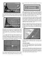
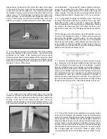
3) It is now time to prepare your electronic speed control
(ESC) for mounting. Solder any required battery connectors to
both the battery pack and ESC, being careful to maintain correct
polarity. With the ESC properly prepared, it can now be installed
into the fuselage. As shown, we mounted our ESC in the battery
compartment, against the right fuselage side, using a 1-1/2 piece
of the provided Velcro
®
tape. Because the adhesive on Velcro
®
tape is not always that aggressive, we suggest gluing the fuselage
piece to the fuselage side with medium or thick CA glue.
❑
4) The receiver is now mounted in the fuselage on top of the
battery tray, again using a 1-1/2" length of the provided Velcro
®
tape. Like the ESC Velcro
®
tape, we, again, suggest using medium
or thick CA glue to secure the tape to the battery tray.
❑
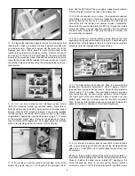
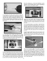
5) With the receiver now in place, the appropriate receiver
connections can be made. Route the rudder and elevator servo
leads up through the oval hole in the battery tray and plug the
connectors into the rudder and elevator receiver receptacles.
Now, route the receiver lead from the ESC up through the slotted
hole in the battery tray and plug the connector into the receiver
throttle channel receptacle. Last, plug the aileron Y-harness into
receiver aileron receptacle.
❑
6) We routed our receiver antenna down through the hole
opposite to the speed control lead and then fed it down along the
inside bottom of the fuselage to the tail. At the tail, we secured the
antenna end to the fuselage with a piece of tape.
❑
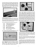
7) The flight battery pack retention strap is now made and
installed into the battery compartment. Cut a 5" length of Velcro
®
tape and then, separate the two pieces. Rejoin the two pieces of
Velcro
®
with a 1-1/2 overlap. This overlapped area is now glued
onto the battery tray as shown using medium or thick CA glue.
The loose ends of the tape should be able to extend over your
battery pack, securing it in place when the two ends are pulled
tight. As shown, this retention strap can secure both 3-stack LiPo
packs as well as the alternative 10-cell NimH flight pack.
❑
8) As shown, the battery pack access hatch is held in place
with a nylon landing gear strap mounted to the fuselage bottom
with a T2.6 x 12 mm PWA screw. Locate these two parts from your
kit contents.
As shown, the mounting position of the nylon strap is centered on
the bottom of the fuselage, 5/16" behind the battery hatch opening.
Properly in place, the strap can be rotated 90
O
, pivoting on the
screw, allowing the hatch to be removed for battery insertion
or removal. Use a 1/16" bit to drill a pilot hole for the PWA screw


