.
TAIL SURFACES
NOTE: The design of the stabilizer-fuselage joint includes a simple method of insuring proper incidence alignment of the
tail. Make sure you understand it before proceeding. Study the pictures and drawings. The 1/4" sq. main frame of the
stabilizer in the center at front and back is left exposed in order that it can be mounted directly on the fuselage. The front
1/4" sq. main frame area sits on the top of F-6. The rear 1/4" sq. main frame area sits on the top of the tab at the end of
fuselage side. The result is a keying of the fuselage and stab together with zero incidence.
108.
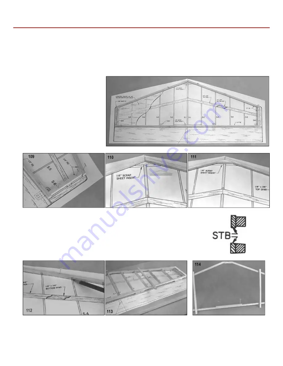
Build the 114" sq. balsa main frame of the horizontal stabilizer directly on the plan.
(The grey toned area of the drawing
indicates the main frame outline.)
109.
Note that the tip pieces of 1/4" sq. are
inset to allow space for later installation
of rib S-6.
110.
Cut a piece of 1/4" sq. to fit in the center
joint of the leading edge.
111.
Glue in place.
112.
Mark the locations of all ribs, front and back, on the 1/4" sq. main frame.
113.
a. Tack glue a temporary scrap balsa cross brace across the top of the 1/4"
sq. stabilizer main frame on each side.
114.
Remove the frame from the board and glue piece STB in place. (See cross
section drawing)
115.
Place scrap 1/4" sq. standoff pieces on the plan in eight different locations, as shown by the arrows.
116.
Return the main frame to the board, this time pinning it on top of the standoff pieces.
117.
Bevel the rib fronts to fit the taper of the leading edge. Glue the ribs into the main frame.


