Typically a modern .25 size engine, (like the Norvel .25), will fly with
a 9 x 4, 9.5 x 4.5, or 10 x 4 propeller. A .35 or .40 size engine will
fly with a 10 x 5 or 10 x 6 prop. Ultimately, final propeller selection
is a matter of testing in flight. Refer to your engine manufacturer’s
instructions for more guidance in selecting a suitable propeller.
CONTROL LINES (not supplied)
The Primary Force should be flown on .015” dia. x 60 - 63 ft. long
braided steel cable control lines.
NOTE ON “LAP TIMES”
Most serious C/L stunt fliers tailor their line length, prop selection,
and engine run to give them a certain airspeed. They check their
airspeed by using a stop watch to find out how long it takes the
airplane to fly one lap of normal level flight. Our flight tests indicate
that the Primary Force flies best at lap times of 5.0 - 5.3 seconds.
COVERING MATERIAL
Your Primary Force has been professionally covered with SIG
AEROKOTE
®
iron-on plastic covering material.
The colors used on the Primary Force are AEROKOTE
®
#SIGSTL321 Bright Orange, and
#SIGSTL100 Brilliant White
Wrinkles In The Covering! After you remove the covered model
parts from their plastic bags, you may notice within the first couple
days that some of the covering material may become slack or
wrinkled. If that's the case, there is no need to be alarmed. The
covering is not defective! Your Primary Force was covered in a
part of the world which has consistantly high humidity and some
of that moisture is retained in the balsa wood when the parts were
put in the bags. When exposed to drier air, the wood loses the
excess moisture, dimensionally shrinking slightly in the process.
In turn, this shrinkage may cause some slight relaxing of the
covering, causing wrinkles to appear.
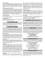
Any wrinkles that appear in the covering are easy to remove by
applying a little heat from a modeler's “covering iron” or small “trim
seal” iron. Be very careful if you are using a “heat gun” to tighten
up loose covering. A heat gun spreads the heat over a very large
area and can cause seams to “crawl” if you are not careful.
The best procedure is to first use a small trim seal iron to go over
all the seams and color joints in the covering, making sure they
are all sealed down and well adhered. Then, hold the hot iron over
the wrinkle to lightly shrink the material - do not press on it. Once
the covering is tight, lightly iron it back down to the wood. Use
caution whenever the hot iron gets close to a seam in the
covering. Over-heating a seam can cause the covering to creep,
exposing the wood underneath.
For reshrinking AEROKOTE
®
set your iron temperature to
approximately 220
O
- 250
O
F (104
O
- 121
O
C).
1
INTRODUCTION
Congratulations on your purchase of the SIG Primary Force ARF.
The reason for the name "Primary" is that this contest winning
stunt ship is really easy to build, trim, and fly.
It makes an
excellent model for the beginning stunt flyer and expert alike. It will
teach you the basic trimming skills needed to be a competitive
stunt flyer without the complexity of a flapped model. Most experts
that have flown the Primary Force like it for its simplicity and praise
it for its honest and superb flying characteristics. The Primary
Force can fly the entire AMA stunt pattern with a level of
smoothness and "flow" that has up to now only been associated
with flap-equipped stunt ships. The Primary Force is equipped
with all the modern day trimming devices and can be flown with
many of the existing .25 to .40 stunt engines.
EASY TO ASSEMBLE
Assembly of your Primary Force ARF is fast and simple when
following the detailed instructions in this manual.
A low parts
count and professional engineering ensure quick and easy
assembly. All parts are CAD-drawn and laser-cut, which means
that everything fits the way it should. The airplane has been
carefully jig built, yielding a straight and true airframe. The light
weight structure is covered and finished in SIG AeroKote
®
polyester film.
We urge you to read through this instruction
manual first, before starting assembly, to familiarize yourself with
the various aircraft parts and assembly sequences.
Technical Specifications PRIMARY FORCE
Wing Span:
50.8 in.
1290 mm
Wing Area:
500 in.
2
32.3 dm
2
Length:
39.5 in.
1003 mm
Flying Weight:
36 - 40 oz.
1020 - 1134 g
Wing Loading:
10.4 - 11.5 oz./ft.
2
31.6 - 35.1 g/dm
2
ENGINE (not supplied)
The Primary Force ARF was designed for light weight 2-stroke
glow engines in the venerable "Fox .35 Stunt" power range. In this
modern era that can include many fine engines from .25 cu. in. up
to .40 cu. in. (4.1 - 6.5 cm
3
). The choice is yours, based on your
personal preference and availability.
For the record, we’ve seen the Primary Force design powered by
the following engines (old and new), all with excellent results: Fox
35 Stunt, OS Max 35S, McCoy 35/40 Redhead, OS 25FP, OS
25LA, OS 40FP, OS 40LA, Brodak 40. Here at the SIG factory, we
have also been using the Norvel .25 BIG MIG and the Norvel .25
BB AME engines with good results.
PROPELLER (not supplied)
Due to the wide range of suitable engines for the Primary Force, it
is impossible to recommend one “best” propeller for all situations.


