12
METHOD 2 (4-5 cell pack):
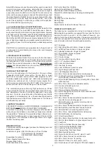
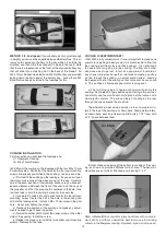
If your battery pack is small enough
in height you can use the supplied plywood Battery Tray. This al-
lows you to secure your battery to the tray while it is outside the
airplane, and then slide the entire unit in place in the nose. Note
that there is a tapered tab at the front of the plywood battery tray
that will slide into a matching slot in the back of the firewall. An
M3 x 12mm Socket-Head Bolt and M3 Flat Washer are provided
bolting down the back end of the battery tray - notice that a M3
Blind Nut is already installed in the fuselage for this.
COWLING INSTALLATION
For this section you will need the fuselage and:
(1) Fiberglass Cowling
(4) M3 x 10mm Screws
❑
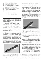
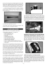
34) Mount the cowling on the fuselage with the four M3 x 10mm
Screws provided. Notice that the holes for the four cowl mounting
screws are already pre-drilled in the cowling - two on each side.
a) First test fit the cowling on the fuselage. As you pass it over
the motor, make sure all the wires are out of the way. Carefully
adjust the exact position of the cowling. Make sure you have ad-
equate clearance between the front of the cowl and the back of
the propeller, and that the prop shaft is centered in the hole. Use
low tack tape to hold the cowling in place for the next step.
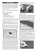
b) Use a 5/64" or #45 bit to drill a pilot hole for the top left cowl
mounting screw. Center the drill in the hole in the cowling and
drill into the fuselage side. Install an M3 x 10mm screw in the pilot
hole - do not over-tighten the screw.
c) Recheck the position of the cowling and make any adjust-
ments needed to get it back in position.
d) Now drill another pilot hole for the upper screw on the other
side of the cowling. Install the screw.
e) Repeat this process to install the two bottom cowl mounting
screws. Remove all the tape.
COOLING IS VERY IMPORTANT!
❑
35) With a fully cowled motor, it is very important to make sure
your motor is getting properly cooled. Air must be able to flow into
the cowling, past the motor, and then back out. It is not enough
to have a lot of air going into the cowling. The flow of air must
also have a way to get out. In fact it’s a good rule of thumb to al-
ways have more air exit area than inlet area to create a positive
air flow through the cowling - an actual suction effect - drawing
the heated air out of the cowling so that more cool air can come
in. This positive air flow keeps your motor running cool.
a) The first thing to do is to figure out how air will get into the
cowling. Some electric flyers decide against using a big spinner,
and simply use the small acorn style prop nut that comes with
most electric motors. This allows plenty of cooling air to enter
through the space around the prop hub.
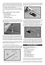
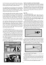
The alternative, when using a spinner, is to cut a couple air in-
lets in the top of the cowling, as shown here. We made two inlets,
as shown here, each one measuring 3/8" wide x 1-1/2" long, with
a 1/2" space between them.
b) Next make an opening at the bottom rear edge of the cowl-
ing, as shown, to provide additional air exit area. The exact di-
mensions are not critical. We made our opening 2” x 2”.
Note: A Dremel® Tool, or similar rotary hand-tool, with an assort-
ment of bits is without a doubt the best tool to use for making
cutouts in the fiberglass cowling. However, if you do not have ac-


