EAN-FLIR Cameras
© SightLine Applications, Inc.
19
8
RHP-BOSON Interface Module - FLIR Boson Camera
This section discusses the FLIR Boson camera and the
RHP-BOON VPC TTL Interface Module
International (PN: RHP-BOS-VPC-TTL-IF).
8.1
Configuration Example - 1500-OEM
Power is supplied externally on the RHP interface module. The analog video is processed through the
1500-OEM. Command and control are established through the following methods:
•
Serial-to-serial or Ethernet-to-serial passthrough
•
Camera configuration - FLIR GUI
•
User implementation of the FLIR Boson command packet (FLIR Serial Line Packet FSLP)
•
Raw bytes (in hex) sent to the camera - Panel Plus main menu
File
»
Send Command
Commands Can be combined into a MACRO for easy reuse during bench setup. They can also be
combined in a LUA script and sent.
Additional technical documentation can be found the
8.1.1
Hardware Connection
Table 2
and
Figure 19
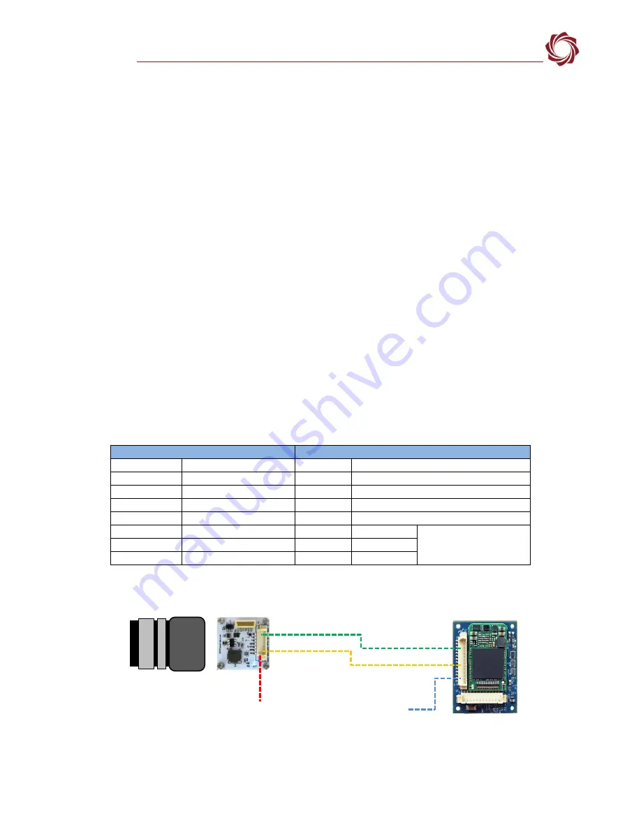
below show an example of how the RHP-BOSON interface module can be
connected to the 1500-OEM. Serial connections are 3.3V TTL on both the 1500-OEM and interface
module. Analog video is NTSC. Power to the interface module can be supplied externally.
Table 2: Connection Example RHP-BOS to 1500-OEM (J3)
RHP-BOSON VPC TTL Interface Module
1500-OEM
P3 (Pins)
Description
J3 (Pins)
Description
1
Vin (+5V DC)
2
Ground
3
Analog Video Out
1
Analog Video In (Cam0)
4
Ground
2
Ground
5
RX »
6
Serial Port 0
6
TX «
5
7
Ground
7
Ground
Figure 19: RHP-BOSON VPC TTL Interface Module - 1500-OEM Example
RHP-BOSON VPC TTL
Interface Module
Ethernet / PWR
FLIR Boson
1500-OEM
J3
P3
PWR
Analog Video
TTL Serial


