EAN-FLIR Cameras
© SightLine Applications, Inc.
4
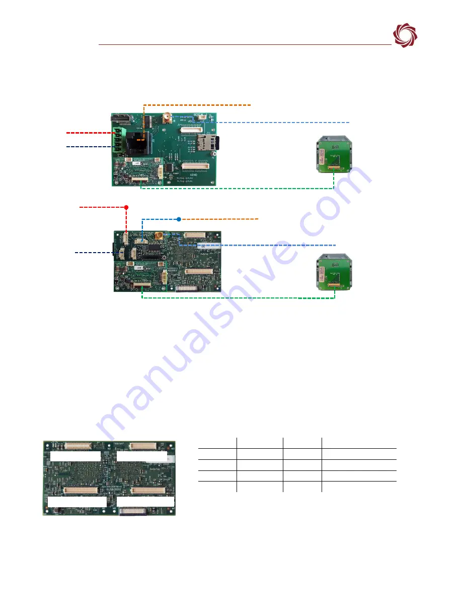
Power and network connectivity LEDs:
A green light on the 3000-IO or 3000-mIO board indicates that all boards are powered on. An amber
light on the 3000-OEM board verifies network connection.
Figure 3: 3000-OEM - Tau Camera Bench Setup
Hardware connections notes:
•
The 3000-OEM can be configured to accept either the digital or the analog output of the Tau
cameras. SightLine recommends using the digital output from the camera to be able to capture IR
temperature data along with camera video data.
•
The digital video connection is through the SLA-3000-FPC adapter board. Analog video connection
is done through an SMA connector on the SLA-3000-AB analog adapter board.
•
Reference the
ICD-OEM-Camera Side Interfaces
connecting the video processing boards to the Tau through the FPC interface boards.
3000-OEM SLA-3000-IO Serial Port Camera Index
Panel Plus
J1
0/1
NA
J2
VOUT
4
NA
J3
VIN0
2
CAM0/CAM1
J4
VIN1
3
CAM2
Figure 4: 3000-OEM Serial Port and Connector Reference
J1 - Serial Port 0/1
J2 - Serial Port 4
J4/VIN1 - Serial Port 3
J3/VIN0 - Serial Port 2
SLA-3000-IO +
3000-OEM
Boards (stacked)
Network Switch or PC Direct
SLA-PWR-C12V
RJ45 Ethernet
Analog
Monitor
(optional)
Video Out
SLA-3000-FPC
on VIN1
SLA-CAB-FPC04
FLIR Tau with
SLA-FPC-TAU
Network Switch or PC Direct
SLA-CAB-0403 (J4)
SLA-3000-OEM +
SLA-3000-mIO+
SLA-3000-FPC
SLA-3000-FPC
on J4
SLA-3000-mIO
on J1
SLA-CAB-FPC04
Analog
Monitor
(optional)
SLA-PWR-B12V
FLIR TAU with
SLA-FFC-TAU
Serial (alternate)
Serial (0)
RJ45 Ethernet
SLA-CAB-1504 (J9)
All boards are
immediately
powered on when
power is connected.


