EAN-FLIR Cameras
© SightLine Applications, Inc.
9
Power and network connectivity LEDs:
A green light (D1) on the 4000-OEM board indicates that all boards are powered on. An amber light
(D5) verifies network connection.
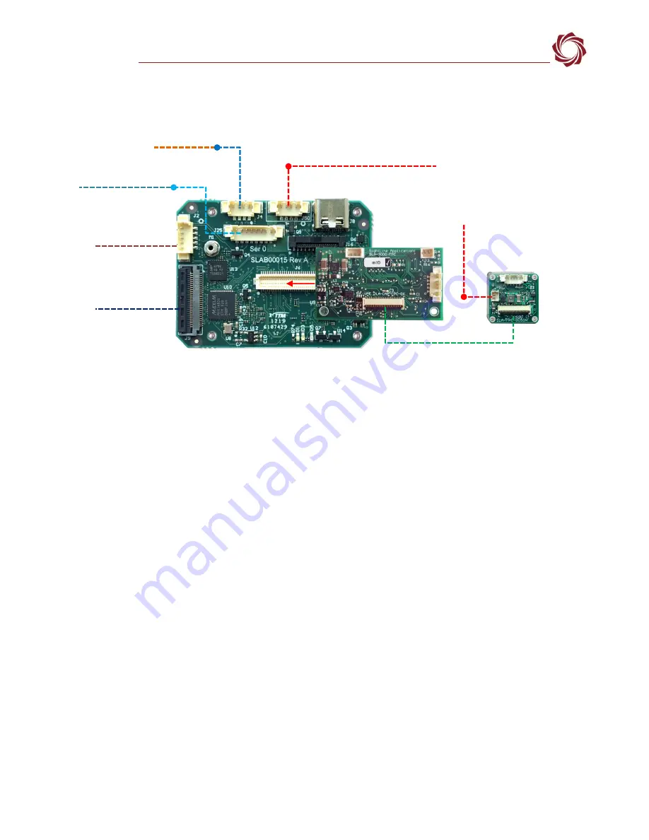
Figure 9: 4000-OEM - Boson Camera Bench Setup
*
SLA-CAB-MIPI-02 FFC cable must be connected correctly. See
instructions before connecting the SLA-4000-MIPI board.
**
SLA-CAB-0305 can connect to SLA-CAB-0804 to facilitate a PC/USB connection to serial port 0 on the 4000-OEM. See the Serial
Communications section in the
Hardware connection notes:
•
For the Boson 320 camera, the
camera board is available without the J2 external
camera power connector. In this configuration the 4000-OEM supplies power to the camera
through the SLA-3000-FPC board.
•
The digital video connection is through the SLA-3000-FPC adapter board. Analog video connection
is done through an SMA connector on the SLA-3000-AB analog adapter board.
•
Reference the
ICD-OEM-Camera Side Interfaces
connecting the video processing boards to the Tau camera through the FPC interface boards.
4
FLIR Neutrino Camera
4.1
Hardware Bench Setup 1500-OEM
Interface and adapter boards:
•
: Neutrino camera and SLA-1500-FPC interface.
•
: Neutrino camera and
interface. The 1500-OEM supplies power to the
camera through the SLA-1500-FPC board.
•
: Provides serial and network interfaces.
Network Switch or
PC Direct
SLA-CAB-1504 (J50)
Serial (SLA-CAB-504)
SLA-CAB-0403 (J4)
4000-OEM +
SLA-3000-FPC
Optional
SLA-4000-MIPI Board
RJ45 Ethernet
SLA-PWR-B12V-36W
**
USB to Serial SLA-CAB-0305 (optional)
SLA-CAB-0804 (J25)
(J6)
SLA-CAB-FPC04
*
SLA-CAB-MIPI-02 (J9)
FLIR Boson with
SLA-FPC-BOSON-E
All boards are immediately powered
on when power is connected.
(J2) Camera PWR
(J8) USB-C


