background image


Manual 

Copyright ©Sigicom AB 2018             Art.no ML089B02850-0En 


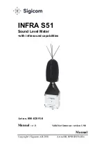
INFRA S51 

Sound Level Meter  
-

with infrasound capabilities 


Art no. 080-02851-0 


Manual 

ver. B   

                     Valid for firmware version 1.9.0 


Summary of Contents for 080-02851-0

Page 1: ...Manual Copyright Sigicom AB 2018 Art no ML089B02850 0En INFRA S51 Sound Level Meter with infrasound capabilities Art no 080 02851 0 Manual ver B Valid for firmware version 1 9 0...

Page 2: ...red operation Canadian customers This Class B digital apparatus complies with Canadian ICES 003 Cet appareil num rique de la classe B est conforme la norme NMB 003 du Canada EU customers This equipmen...

Page 3: ...tion and operation 14 4 1 Random incidence microphone 14 4 2 Mounting 15 4 3 Pressure reflection phenomena 15 4 4 Parameters 17 4 5 Measurements of low level sounds 20 4 6 Quick Start 21 4 7 Periodica...

Page 4: ...Copyright Sigicom AB 2018 3 A 7 Power consumption 32 A 8 Mechanical data 33 A 9 Approvals 33 Appendix B Glossary 34...

Page 5: ...with infrasound capabillities The S51 Sound Level Meter is to be integrated with the INFRA Field Monitoring System See one example of this in the figure here below Example of a setup of the INFRA Fiel...

Page 6: ...nting description and detailed description of S51 s standards and parameter settings It also includes a Quick start guide and how periodical testing is performed Chapter 5 Consider this Important info...

Page 7: ...the database Possibility to connect more than one sound level meter to each Datalogger Selectable time interval of the interval data A trigger level for recording a sound clip transient with up to 10...

Page 8: ...rtage to Sigicom AB Record the instrument s serial number You will be asked to give this number in any S51 related communication you may have with Sigicom AB 1 4 Safety Do never attempt to disassemble...

Page 9: ...pose acoustic measurements especially suitable to use in diffuse sound fields The microphone has a large dynamic range and a wide frequency response The S51 Sound Level Meter is to be connected to the...

Page 10: ...usly with the sound pressure level measurements for example vibration geophone in one direction vibration geophone in three directions air blast dust monitoring wind speed and direction air temperatur...

Page 11: ...pressure peaks Leq The time averaged sound pressure level over the selected interval time see below It has the formal symbol LAT IEC 61672 1 but for mainly historical reasons LAT is commonly referred...

Page 12: ...Lmax in this case and only use Lmax data if when frequecies closer to the upper 20Hz band is the main contributor 3 4 Level ranges S51 Sound Level Meter handles the level ranges 20 95 dBA 25 95 dBC 30...

Page 13: ...ger fires a manual trig Recording post trig length is adjustable between 1 and 10 seconds Pre trig is always 1 second Transient data The microphone signal is tapped from the signal chain before the we...

Page 14: ...o the same Datalogger shares the transfer channel If the recording length is set short the transient memory will be splitted into two or more transient files This enables that more than one transient...

Page 15: ...in the sound field The most ideal frequencies response is reached when the microphone is pointed 90 degrees off the direction of the sound source At normal diffuse field measurements the S51 shall be...

Page 16: ...when the S51 Sound Level Meter is to be mounted to a wall see picture below The distance between the wall and the center line at the top of the microphone is then 15 mm S51 Sound Level Meter mounted...

Page 17: ...17 mm between the center of the microphone and the wall The illustrated pressure level is relative to what should have been measured without any reflections Note that a maximal distance of 15 mm is a...

Page 18: ...15 dBA S04 Lmax and Leq FAST 55 130 dBA S05 Lmax and Leq FAST 25 95 dBC S06 Lmax and Leq FAST 30 105 dBC S07 Lmax and Leq FAST 40 115 dBC S08 Lmax and Leq FAST 55 130 dBC S09 Lpeak and Leq PEAK 60 130...

Page 19: ...und pressure level of the Lmax Lpeak channel becomes larger than its upper threshold level the the Lmax Lpeak signal is recorded in a transient file The INFRA functionalities SMS and Server messages c...

Page 20: ...cribed above It can be selected from 1 to 10 seconds with the alternatives 1 2 3 4 5 6 8 and 10 s A pre trig time of one second is always included in the beginning of the recording 4 4 6 Customer stri...

Page 21: ...ise and the measured sound can be considered as uncorrelated and don t add directly to each other The self generated noise level for the less sensible ranges is higher but is at least 5 dB below the l...

Page 22: ...the chosen standard select Interval time Record time and Upper threshold level value and on off It is also possible to change the customer string Note When doing a test or reference measurement be su...

Page 23: ...NFRA Datalogger see instruction below to read the current sound pressure level the first value is not valid due to start up effects Press live several times to be sure that the value is stable The dis...

Page 24: ...shipped care should be taken in repackaging it with the original factory provided packaging S51 shall never be subjected for sound pressure levels above 146 dB Note that maximum measured sound pressur...

Page 25: ...ata Post processing can be done in the web application InfraNet Data is sent from the Datalogger to an Internet accessible database server where each Infra customer has its own database instance See f...

Page 26: ...to Sigicom AB for calibration and adjustment See contact information below Recommended calibration interval is 12 months If sent to repair please carefully write down the description of the problem It...

Page 27: ...80 01710 0 to 080 01714 0 Sensor bolts of different lengths For mounting of the S51 Sensor Level Meter on a wall Possibly used together with the Mounting Wedge see below Expansion Plug Sigicom art no...

Page 28: ...he S51 Sound Level Meter shall be mounted to a wall By using the Mounting Wedge the sensing microphone will come very close to the wall which is a requirement in many cases Acoustic calibrator Class 1...

Page 29: ...0m 6 6ft art no 080 01102 0 Sensor drop cable 5 0m 16ft art no 080 01105 0 Sensor cable 15m 49ft art no 080 01115 0 Sensor cable 40m 131ft art no 080 01140 0 Sensor cables in other lengths on special...

Page 30: ...E 12545 LVSJ Sweden Phone 46 8 4499750 Web http www sigicom com Support Phone 46 8 44 99 770 Email support sigicom com Web http support sigicom com infra USA Sigicom Inc 2649 East Mulberry Stress Unit...

Page 31: ...ressure 101 3 kPa Direction not important A 2 Accuracy S51 follows the requirements for class 1 sound level meters which implies that it is capable to measure the sound pressure level of a sinusoidal...

Page 32: ...128 55 131 55 131 55 129 55 127 100 S10 60 130 dBC 60 128 60 131 60 131 60 129 60 127 100 Standard Level Range and Frequency weighting 1Hz lower upper 5Hz lower upper 10Hz lower upper 20Hz lower upper...

Page 33: ...hone and the electronics inside the S51 Under no conditions voltages above 10Vp p may be applied to the input adapter Use a high quality signal generator A 6 Overload handling Interval values are tagg...

Page 34: ...ions Gore Tex vent for pressure equalization of the microphone Dimensions 80 x 300 x 50 mm Protection class equivalent to IPx6 3 8 16 UNC thread for mounting on camera tripod Weight 750 g A 9 Approval...

Page 35: ...ifferent combinations of the parameters Acoustic quantity Time weighting Level range Frequency weighting Transient file If the measured signal becomes larger than the upper threshold level the Lmax Le...

Reviews: