background image


Copyright © Sigicom AB 2021 


32 

5.8.7.


Errors and Warnings 

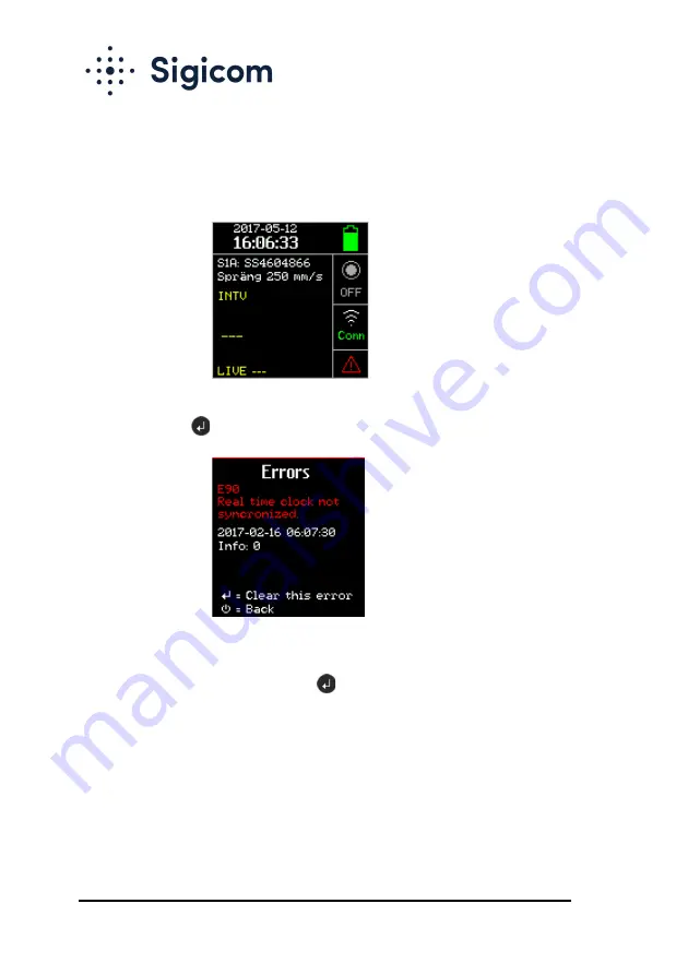
A yellow or red triangle at the bottom right of the main screen indicates 
that an error code is set. 


For viewing and resetting of the errors codes, select Errors in the GUI 
menu, and press 

 . 


Errors are in red text, and warnings in yellow. If there are several errors, 
use the arrow keys to scroll between them. Each individual error code can 
be acknowledged / cleared with the 

 key. 

A list of errors and warnings is presented in Appendix E. 


Summary of Contents for 080-05220-0

Page 1: ...Manual Copyright Sigicom AB 2021 Art no ML089 05220 0En INFRA C20 Wireless Vibration Monitor Art no 080 05220 0 Manual ver N Valid for firmware 2 5 1 ...

Page 2: ...ts than applicable Sigicom products A power source connected to the C20 must not be able to supply more than 20V and 3A A solar panel with maximum 25W power and with an open circuit voltage of 22V is allowed Replacement and other handling of the batteries shall only be executed by persons who have carefully read the instructions in this manual Never keep the batteries at temperatures above 50ºC 12...

Page 3: ...itoring and control instruments Scrapped equipment should be sent back to the manufacturer of the equipment Sigicom AB for proper handling according to the WEEE directive Sigicom uses a certified local partner for recycling of scrapped equipment The batteries used in this equipment falls under the Battery Directive 2006 66 EC When the equipment is sold to customers in the European Union EU except ...

Page 4: ...ration Sensor 15 3 1 2 Analog Electronics 15 3 1 3 Analog Digital Conversion 15 3 1 4 Digital Signal Processing 15 3 2 Measuring Logic 16 3 2 1 Measurement Standards 16 3 2 2 Interval Measurements 16 3 2 3 Transient Recording 17 3 2 4 Overload Handling 17 3 3 Data Storage 18 3 3 1 Transient Data 18 3 4 Additional Hardware 18 3 4 1 Humidity Sensor 18 3 4 2 GPS Receiver 18 4 Configuration and Instal...

Page 5: ...2 Communication Mode 27 5 8 3 Clock Set 28 5 8 4 Clock format 28 5 8 5 USB Memory Interface Mode 29 5 8 6 Firmware Upgrade 30 5 8 7 Errors and Warnings 32 5 8 8 Power Off and Reboot 33 5 9 GUI Passcode 34 5 10 INFRA Net Remote Control 35 5 10 1 Remote Firmware Upgrade 36 5 10 2 Remote Reboot 36 5 10 3 Remote Shut Down 37 5 10 4 Remote Update GPS Position 37 6 Other Functions 38 6 1 Disable Communi...

Page 6: ...atteries 47 Appendix D In Case of Li Ion Battery Fire 48 Appendix E Errors and Warnings 49 Appendix F Measurement Standards 50 Appendix G Configure APN 55 Appendix H Enter SIM PIN code 56 Appendix I Configure PPP authentication 58 Developed and manufactured by Sigicom AB Glasfibergatan 8 SE 124 45 Älvsjö Sweden Support support sigicom com ...

Page 7: ... error event has occurred Manual communication is performed by the operator At scheduled communication 1 2 INFRA C20 Vibration Monitor The C20 instrument is a complete wireless vibration monitor measuring in vertical direction It consists of vibration sensor elements analog measuring electronics analog digital converters an embedded microcontroller DSP for digital signal processing etc a small col...

Page 8: ... memory card and SIM card but will seldom need to be opened A separate hole at the lower left side of the unit may be used for a wire to lock the unit to a fix and solid structure for theft prevention Three mounting setoff screws located on the back of the instrument enable sufficient secure and plumb contact between instrument and uneven vertical or near vertical surfaces These screws are not use...

Page 9: ...C20 Vibration Monitor instrument Foam shock protection during transportation Two 2 batteries either inserted in unit or separate Note Because of shipping regulations batteries are charged below 30 state of charge at delivery Calibration document Any damage or omission should be reported immediately to Sigicom Keep record of the instrument s serial number You will be asked to give this number in an...

Page 10: ...it Display ON Exit Cancel Display OFF Up Increase Down Decrease Monitoring start stop Communication status Menu Enter Acknowledge Activate For more information about operation of the graphical user interface see chapter 5 Operation Note The LED indicator the green circle in the picture above is only used at firmware upgrade ...

Page 11: ... screen is divided in six sections 1 STATUS FW files available Date and time GPS time sync enabled external power battery status and charging 2 DATA Measurement standard Vibration data interval INTV or transient EVT values in three directions Live values for three directions maximum over the last three seconds 3 MONITORING status 4 COMMUNICATION status 5 GPS position status 6 ERRORS and WARNINGS S...

Page 12: ... connector is located at the left hand side of the instrument Input for a 12V power supply is supported When the battery level is low the external power will charge the batteries1 For a complete charge the batteries must be removed from the instrument and charged separately Note Use the plastic cap to protect the external power connector when not in use 2 5 USB Connector Micro B Type A Micro USB c...

Page 13: ...e as a removable drive via the USB connector see section 5 8 5 If the memory card is unintentionally missing or corrupt an error message will be displayed at start up see Appendix E Please contact Sigicom Support for guidance regarding memory card formatting or other memory card issues Note Only use a memory card approved by Sigicom 2 7 SIM Cards If activated when ordering the embedded SIM card is...

Page 14: ...ith the cut corner first and to the right Note The PIN code lock of the removable mini SIM card must be deactivated before use in C20 Contact your network provider for pin code lock deactivation For activation or deactivation of the embedded SIM card please contact Sigicom Support ...

Page 15: ...The signal is then low pass filtered with an analog filter to avoid aliasing Then the signal passes through an analog digital converter and all subsequent signal processing is digital 3 1 3 Analog Digital Conversion All sampling is performed at 4096 Hz The analog digital converter has a 16 bits resolution which at measurements up to 250 mm s 10 in s in the largest range provides a minimum resoluti...

Page 16: ...of standard A more thorough description of the available measurement standards is given in Appendix F 3 2 2 Interval Measurements The C20 processes the vibration signal through the filters and detectors of the selected measurement standard The interval value is the maximum value of the processed signal within a selected interval time When the interval end time is reached the maximum value is saved...

Page 17: ...y consumption Lots of data storage on memory card High data transfer rate cost The length of the recording is 1 second before the trigger point plus an adjustable time between 1 and 40 seconds The adjustable time is referred to as Record time in the graphical user interface and Transient time in INFRA Net For the maximum value EVT in the graphical user interface of the channel transients a frequen...

Page 18: ...ndard INFRA Net includes all implemented standard filters 3 4 Additional Hardware 3 4 1 Humidity Sensor The C20 is equipped with a humidity sensor A warning message is sent to INFRA Net if the relative humidity is higher than 95 The last measured value of the humidity can be read in the GUI by selecting Instrument status in the Menu see section 5 8 3 4 2 GPS Receiver The C20 is equipped with a GPS...

Page 19: ...re communication difficulties the unit will continue to communicate until successful using a time delay pattern to minimize power consumption 4 1 2 Flight Mode C20 can be set to run in flight mode where INFRA Net and other communication is inhibited see section 5 8 2 for details 4 1 3 Configuration Menu For setup of monitoring parameters go to the Monitoring configuration menu see section 5 8 1 4 ...

Page 20: ...l to tighten the nut to secure the C20 to the wall If the wall or ground is not completely flat you can adjust one or two of the mounting screws to ensure all three have full contact with the wall Make sure that the C20 is firmly attached and aligned plumb and level For correct measuring results the mounting angle of the instrument must not exceed 5º relative to the horizontal plane Refer to Sigic...

Page 21: ...d be addressed prior to monitoring See section 5 8 7 If last known monitoring mode was ON the C20 will automatically restart monitoring after instrument start up 5 2 Start Monitoring To start monitoring2 press The display will indicate the mode transition and its steps 1 First a sensor test will be done see 5 2 1 This takes a few seconds and the monitoring symbol is yellow during this phase 2 Moni...

Page 22: ... as it should Your instrument is correctly mounted If the test pulse from the vibration sensor indicates error An error symbol will be displayed The error will be communicated to INFRA Net Monitoring will continue The test pulses and analyzed results are saved and communicated to INFRA Net 5 3 Stop Monitoring To stop monitoring assuming display is on press and acknowledge with The monitoring symbo...

Page 23: ...erver and automatically removed from the memory card If there are communication problems the C20 will continue to attempt to communicate with incrementally increasing time intervals between communication attempts 5 4 1 Automatic INFRA Net Communication Automatic communication will be done in the following situations After start or stop of monitoring After a transient recording When an error has be...

Page 24: ...erred to as time out If an activity has taken place e g a key is pressed the time out will be prolonged Note Power off may be inhibited by internal activities such as Monitoring is on Monitoring is stopped but there is a recording on going C20 is communicating with INFRA Net communication Any such activity must be finished before power off is performed For manual power off see section 5 8 8 5 6 Po...

Page 25: ...ee Figure 5 Turn the battery lock lever to one side and remove replace the first battery Turn the battery lock lever to the other side and remove replace the second battery Reset the lock lever in its middle position for the lid to fit Replace the front lid using a Torx T20 driver Figure 5 Instrument with front lid removed ...

Page 26: ...in the following sections 5 8 1 Monitoring config To view and possibly change the monitoring parameters select Monitoring config Monitoring config Frequency weight parameter may also be available as an additional option depending on selected standard Use and to select parameter and to enter the parameter settings screen ...

Page 27: ... 10 5 8 2 Communication Mode Communication mode has two options Normal mode Internet and INFRA Net are available Flight mode Internet and INFRA Net communication are disabled Go to Set communication mode by pressing Settings and actions Communication mode Flight mode will be indicated on the main screen with an airplane symbol ...

Page 28: ... actions Clock set Note To change Clock settings Monitoring must be OFF and Communication mode set to Flight mode Use to step forward and arrow keys or to change a value Finish with the key Note C20 will reboot after the clock is changed 5 8 4 Clock format Time can be displayed in either 12 or 24 hour format which is configured by this selection This configuration is only for the instrument INFRA ...

Page 29: ... USB mode Note To set USB mode Monitoring must be OFF and Communication mode set to Flight mode 1 Have a USB cable connected between a PC and the C20 USB connector see section 2 5 2 Press 3 The microSD memory should now appear as a removable drive in the file system of the PC 4 When finished command the PC to eject the removable disc 5 Disconnect the USB connector from the instrument and it will r...

Page 30: ...unication mode set to Flight mode see section 5 8 2 to perform a firmware upgrade This is the procedure to do this 1 Set the C20 in USB mode see section 5 8 5 step 1 to 3 2 Copy the new firmware a bin file and a meta file to the file system root on the memory card 3 Return from USB mode see section 5 8 5 from step 4 until reboot 4 The copied firmware files will be indicated with FW in the upper le...

Page 31: ...e C20 again Perform a manual communication see section 5 4 2 6 On the main screen wait for the communication to finish which is indicated by Idle displayed below the communication symbol in the display It takes at least two minutes to upload the FW files When the FW files are downloaded this is indicated by the symbol4 in the upper left corner This symbol was introduced in FW version 1 3 0 7 Set c...

Page 32: ...or code is set For viewing and resetting of the errors codes select Errors in the GUI menu and press Errors are in red text and warnings in yellow If there are several errors use the arrow keys to scroll between them Each individual error code can be acknowledged cleared with the key A list of errors and warnings is presented in Appendix E ...

Page 33: ...are reached through the menu system by Settings and actions Power off Reboot Note Monitoring must be OFF when doing power off or reboot Power off Reboot Select either power off or reboot in the list and click If the selected action is permitted you will be asked to confirm once again with ...

Page 34: ...code is then entered on the keypad at start up Use the and keys followed by The default passcode is 1 2 3 It can be entered in the following ways or If the passcode is active at display start up and the passcode is entered incorrectly or not entered at all the C20 GUI will be opened in a view only mode All settings and actions including monitoring start are prohibited An active passcode may be dea...

Page 35: ... change of some parameters e g the trigger level will 1 Cause temporary stop of monitoring 2 Change the parameter s 3 Restart monitoring Other parameters e g the INFRA Net communication schedule can be changed without a monitoring stop restart procedure Also when the instrument is in monitoring off mode the INFRA Net Remote system can be used however physical access is required Use the following p...

Page 36: ...w firmware at the next communication5 and the upgrade will be performed sometime between 3 a m and 5 a m local instrument time 5 10 2 Remote Reboot It is possible to force a reboot restart on an C20 which is at work monitoring vibrations This is done by selecting in INFRA Net Hardware tab Special commands Remote Reboot followed by Manage changes Commit The data logger will perform the reboot at th...

Page 37: ...The data logger will perform the shutdown at the next communication 5 10 4 Remote Update GPS Position GPS position is updated every time Monitoring is started but it is possible to remotely call for an update of the GPS position Please select in INFRA Net Hardware tab Special commands Remote Update GPS Position followed by Manage changes Commit The C20 will perform the update at the next communica...

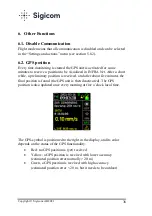
Page 38: ...e a preliminary position is received and after about five minutes the final position is found the GPS unit is then deactivated The GPS position is also updated once every morning at five o clock local time The GPS symbol is positioned to the right in the display and its color depends on the status of the GPS functionality Red no GPS position is yet received Yellow a GPS position is received with l...

Page 39: ...is empty is thus shortened with the same factor 6 4 Time Synchronization through Internet The C20 automatically synchronizes its clock to an NTP Network Time Protocol server on Internet SNTP according to RFC 4330 is used No user configuration of the NTP server can be made An NTP request with subsequent difference calculation is performed at every INFRA Net communication but not more often than onc...

Page 40: ...between daylight saving time DST and standard time STD is configured with the time zone mentioned above The C20 does not need to turn monitoring off during the transition All data from C20 is time stamped with UTC time Daylight Saving Time only affects the presentation of time ...

Page 41: ...o 7 months depending on ambient temperature quantity of transient recordings and scheduled INFRA Net communications etc Backup battery Expected life 5 years Note The Backup battery may only be replaced by Sigicom technician or agent Modem Cellular 2G 3G 4G modem some variations exist Antennas Adjusted for 900 1800 2100 MHz for users within EU and 850 1900 2100 MHz for users in the US Reference Sta...

Page 42: ... outdoor use Note Make sure that any connector or cord used with this power supply is also approved for outdoor use Mounting plate C2x 080 01818 0 External antenna kit future product on request Wire lock part number 080 01830 0 Socket wrench 10 mm with handle part number 080 01893 0 Hex screwdriver 3 mm for plastic antenna cover part number 080 01894 0 Transport case INFRA C2x part number 080 0188...

Page 43: ...o keep the C20 dry and protect the electronics from corrosion check replace the desiccant bag in its compartment regularly It is recommended to check once per year and change every two years If suspicion of any moisture inside the enclosure find the cause dry it out and replace the desiccant bag If sent to repair after damage from moisture please remove both main batteries and the backup battery t...

Page 44: ...AB Postal Glasfibergatan 8 Delivery Älvsjövägen 26 SE 12545 ÄLVSJÖ Sverige Phone 46 8 4499750 Email info sigicom com USA Sigicom Inc 2636 Midpoint Drive Ste B Fort Collins CO 80525 Phone 970 493 1552 Email info sigicom com World wide Support Phone 46 8 44 99 770 Email support sigicom com ...

Page 45: ...ked BAT CRITICAL BAT EMPTY 0 red outline Rising voltage BAT EMPTY BAT CRITICAL 2 red ticked scale ticked outline BAT CRITICAL BAT LOW 7 yellow scale ticked outline BAT LOW BAT NORMAL 17 green scale BAT NORMAL BAT FULL 97 green full scale If one of the two batteries is removed the indicated SOC level will be halved and the warning message BATTERY LOST will will be communicated If the SOC level of t...

Page 46: ...referens Transport of C20 with batteries installed Before air transport set the C20 in Flight mode then select Power off via Settings and actions in the graphical user interface Make sure that the equipment is packed in such a way that the instrument does not start up during transport Use original packaging material an INFRA C2x transport case see chapter 8 Accessories or similar A battery identif...

Page 47: ...and are not in danger of falling to the floor during charging Have foam extinguisher CO2 or ABC dry chemical available on sites where batteries are handled regularly Have fire alarms on sites where batteries are handled regularly Have a metallic bucket half filled with sand available to put batteries into in case of a burning battery Interpret the In case of Li Ion battery fire instruction example...

Page 48: ...OFFICE FIRE ROUTINES SEEK ATTENTION TO A COLLEAGUE FOR STANDING BY WHILE HANDLING THE FIRE REMOVE POWER FROM CHARGER REMOVE THE BATTERY FROM CHARGER DEVICE OR COMBUSTIBLE MATERIAL PLACE THE BATTERY IN SAND FILLED BUCKET PLACE OUTSIDE IF POSSIBLE USE FIRE EXTINGUISHER WATER IS OK IF NO OTHER KIND OF FIRE EXTINGUISHER IS AVAILABLE PUT SEEMINGLY BURNED OUT BATTERY OUTSIDE FOR A TIME ...

Page 49: ...p battery low Contact Sigicom Support E43 Sensortest error Check that the instrument is correctly aligned If it is contact Sigicom Support E81 Monitoring started automatically After instrument reboot E86 Instrument alignment incorrect The instrument shall be mounted horizontally E90 Real time clock not synchronized Check instrument clock9 E91 Real time clock poorly synchronized Check instrument cl...

Page 50: ...1 Komfort RMS 1s 700 mm s2 1 80 Hz S9 DIN 4150 2 KB RMS 125 ms 20 mm s 1 80 Hz S16A Acceleration 125 m s2 5 300 Hz S16B Acceleration 12 5 m s2 5 300 Hz S18A DIN 4150 3 Anlage 250 mm s 1 315 Hz S18B DIN 4150 3 Anlage 25 mm s 1 315 Hz S20A NS 8141 2001 Byggverk 250 mm s 5 300 Hz S20B NS 8141 2001 Byggverk 25 mm s 5 300 Hz S22 NS 8176 Komfort RMS 1s 20 mm s 1 80 Hz S25A NS 8141 2013 Byggverk 250 mm s...

Page 51: ...ärrörande från pålning spontning schaktning och packning för bedömning av skaderisk Level frequency ranges 25 mm s 5 150 Hz Max resolution in presentation 0 005 mm s and 3 significant digits Threshold range 0 04 22 mm s 5 SS 025211 Schakt Vibration och stöt Riktvärden för vibrationer i byggnader härrörande från pålning spontning schaktning och packning för bedömning av skaderisk Level frequency ra...

Page 52: ...ignificant digits Threshold range 0 04 15 mm s 16A Acceleration Mechanical vibration and shock Measurement and evaluation of shock and vibration effects on sensitive equipment in buildings Level and frequency ranges 125 m s2 5 300 Hz10 Max resolution in presentation 0 01 m s2 and 3 significant digits Threshold range 0 1 110 m s2 16B Acceleration Mechanical vibration and shock Measurement and evalu...

Page 53: ...Måling av svingehastighet og beregning av veiledende grenseverdier for å unngå skade på byggverk Level frequency ranges 250 mm s 5 300 Hz Max resolution in presentation 0 05 mm s and 3 significant digits Threshold range 0 4 220 mm s 20B NS 8141 2001 Byggverk Vibrasjoner og støt Måling av svingehastighet og beregning av veiledende grenseverdier for å unngå skade på byggverk Level frequency ranges 2...

Page 54: ...øt Veiledende grenseverdier for bygge og anleggsvirksomhet bergverk og trafikk Del 1 Virkning av vibrasjoner og lufttrykkstøt fra sprengning på byggverk inkludert tunneler og bergrom Level frequency ranges 25 mm s 3 400 Hz Max resolution in presentation 0 005 mm s and 3 significant digits Threshold range 0 04 22 mm s 53A Geophone Unfiltered geophone signal Upper frequency limit 500 Hz Level and fr...

Page 55: ...ettings to require it Therefore it is recommended to set it by Ask your SIM provider which APN should be used with the SIM On a PC make a text file with the name extapn txt with the desired APN in its first and only line 1 Set the C22 in USB mode and copy the file above to the root of the SD card 2 Reboot This will configure the internal APN in the configuration 3 When succeeded the file name abov...

Page 56: ...nit must not be in flight mode If the PIN code is incorrect the remaining number of attempts will be shown when the connection fails If a wrong PIN code has been used three times the SIM card will require the PUK code together with a new PIN code to unlock This will also be clearly shown in the communication menu when a connection fails If needed a PUK code can also be entered When entering the PU...

Page 57: ...the PUK code is not Note The unit will only try a PIN code or PUK code once This is to avoid accidentally locking the SIM card if multiple connections are attempted Therefore it is safe but useless to retry a connection with an incorrect PIN code that has already been tested ...

Page 58: ...t in USB mode and copy the file above to the root of the SD card 3 Reboot This will configure the PPP username and password 4 When succeeded the file is automatically removed from the SD card 5 When configured the PPP username can be viewed in the SIM information menu from the main screen press COMM ENTER DOWN The password length can also be seen but the actual password is hidden Note that this in...

Reviews: