background image


8                                                                                             

SAP2500D  Differential  Probe  User  Manual


2.3  Quality Assurance 

Probes and accessories have a 1-year warranty from the date of shipment, 

during normal use and operation. SIGLENT can repair or replace any product 

that is returned to the authorized service center during the warranty period. We 

must first examine the product to make sure that the defect is caused by the 

process or material, not by abuse, negligence, accident, abnormal conditions, 

or operation. 


SIGLENT shall not be responsible for any defect, damage, or failure caused by 

any of the following: 

a)  Attempted repairs or installations by personnel other than SIGLENT. 

b)  Connection to incompatible devices/incorrect connection. 

c)  For  any  damage  or  malfunction  caused  using  non-SIGLENT  supplies. 

Furthermore, SIGLENT shall not be obligated to service a product that has 

been  modified.  Spare,  replacement  parts,  and  repairs  have  a  90-day 

warranty. 


2.4  Maintenance Agreement 

We provide various services based on maintenance agreements. We offer 

extended warranties as well as installation, training, enhancement and on-site 

maintenance, and other services through specialized supplementary support 

agreements. For details, please consult your local SIGLENT customer service 

center or distributor. 

Summary of Contents for SAP2500D

Page 1: ...SAP2500D Differential Probe User Manual EN01A...

Page 2: ......

Page 3: ...4 1 4 CLEANING 4 1 5 ABNORMALITIES 4 2 FIRST STEPS 6 2 1 DELIVERY CHECKLIST 6 2 2 FUNCTIONAL CHECK 6 2 3 QUALITY ASSURANCE 8 2 4 MAINTENANCE AGREEMENT 8 3 MECHANICAL DIMENSION 9 4 ACCESSORIES 10 5 PR...

Page 4: ...ating this accessory is the responsibility of the assembler of the system Connect and disconnect properly Connect the probe to the measurement instrument before connecting the test leads to a circuit...

Page 5: ...nt it is connected to Attend to the accompanying information to protect against personal injury or damage Do not proceed until conditions are fully understood and met 1 2 Operating Environment The acc...

Page 6: ...ervice 1 4 Cleaning The exterior of the probe and cable should be cleaned using a soft cloth moistened with water The use of abrasive agents strong detergents or other solvents may damage the probe Al...

Page 7: ...connect the probe from the oscilloscope To use the probe correctly all instructions and markings should be read carefully WARNING Using the probe in a manner not specified by the manufacturer may dama...

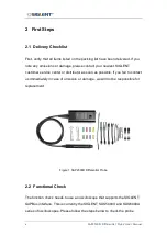
Page 8: ...service center or distributor as soon as possible If you fail to contact us immediately in case of omission or damage we will not be responsible for replacement Figure 1 SAP2500D Differential Probe 2...

Page 9: ...d attenuation ratio 4 Select the channel to which the probe is connected Set the oscilloscope scale factor to 1 V div Set the oscilloscope offset factor to 0 V 5 Measure the average voltage of channel...

Page 10: ...ure caused by any of the following a Attempted repairs or installations by personnel other than SIGLENT b Connection to incompatible devices incorrect connection c For any damage or malfunction caused...

Page 11: ...ser Manual 9 3 Mechanical Dimension Characteristic Description SAPBus interface box 115 0 mm 38 9 mm 24 5 mm Probe head 100 0 mm x 12 0 mm x 10 0 mm Tip Pitch 2 54mm Cable length 1 3 m from the probe...

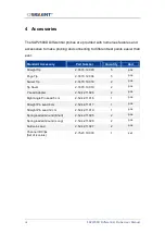
Page 12: ...2 74 70 12 003 5 pcs Pogo Tip 2 74 70 12 004 5 pcs Swivel Tip 2 74 70 10 018 2 pcs Tip Saver 2 74 70 10 019 2 pcs Y Lead Adapter 2 52 42 11 026 2 pcs Right Angle Pin Lead 5 cm 2 52 42 11 016 1 pcs St...

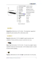
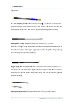
Page 13: ...socket Pogo Tip Part Number 2 74 70 12 004 The pogo tip provides z axis compliance The tip can fit into a socket or via and onto an IC leg Swivel Tip Part Number 2 74 70 10 018 The swivel tip adapter...

Page 14: ...2 52 42 11 017 12 cm 2 52 42 11 019 These leads have a socket on one end and a square pin on the other to connect to the input or ground socket of the probe body and may be used for general purpose p...

Page 15: ...ttached to either socket of the probe head Solder in Lead Part Number 2 52 42 11 027 This lead is designed to be soldered directly to the test points for a secure connection A damping 56 2 resistor is...

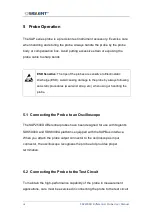
Page 16: ...always following anti static procedures wear wrist strap etc when using or handling the probe 5 1 Connecting the Probe to an Oscilloscope The SAP2500D differential probes have been designed for use wi...

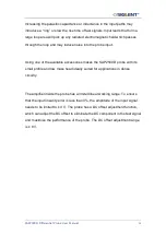
Page 17: ...one of the available accessories makes the SAP2500D probe with its small profile and low mass head ideally suited for applications in dense circuitry The amplifier inside the probe has a limited linea...

Page 18: ...he SAPBus interface the SAP2500D becomes an integral part of the oscilloscope measurement circuit The probe can be controlled from the oscilloscope s front panel The oscilloscope provides power to the...

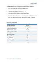
Page 19: ...in a thermally stable environment and the probe and oscilloscope should be warmed up for at least 20 minutes Warranted characteristics Characteristics SAP2500D Bandwidth probe only 2 5 GHz Bandwidth...

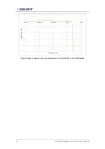
Page 20: ...18 SAP2500D Differential Probe User Manual Figure 3 Typical system frequency response of the SAP2500D and an SDS6204A...

Page 21: ...SAP2500D Differential Probe User Manual 19...

Reviews: