SDG6000X User Manual 119
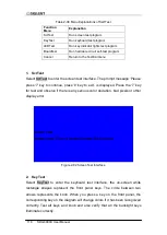
Figure 2-83 Key Test Interface
The corresponding area of tested keys or knob changes to in a blue when
a key press is recognized.
The top of the screen displays „Please press „8‟ key three times to exit.‟
3. LED Test
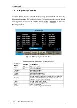
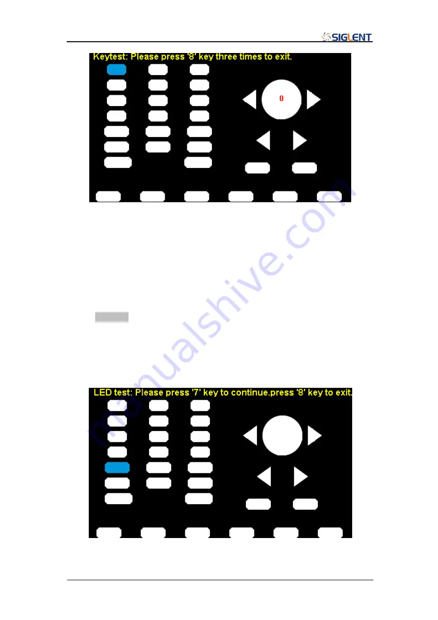
Select LEDTest to enter the LED test interface, the on-screen white rectangle
shapes represent the front panel keys. The prompt message
„Please press „7‟
Key to continue, p
ress „8‟ Key to exit.‟ is displayed. Press the „7‟ key
continuously for testing and when a key is lighted, the corresponding area on
the screen will display in a blue color.
Figure 2-84 LED Test Interface
Summary of Contents for SDG6000X Series
Page 2: ......
Page 45: ...SDG6000X User Manual 35 Figure 2 16 Setting the Bandwidth...
Page 142: ...132 SDG6000X User Manual Figure 2 95 Phase Deviation Interface...
Page 160: ...150 SDG6000X User Manual Figure 3 1 Generate a Sine Waveform...
Page 162: ...152 SDG6000X User Manual Figure 3 2 Generate a Square Waveform...
Page 175: ...SDG6000X User Manual 165 Figure 3 9 Generate an AM Modulation Waveform...
Page 177: ...SDG6000X User Manual 167 Figure 3 10 Generate a FM Modulation Waveform...
Page 179: ...SDG6000X User Manual 169 Figure 3 11 Generate a PM Modulation Waveform...
Page 181: ...SDG6000X User Manual 171 Figure 3 12 Generate a FSK Modulation Waveform...
Page 183: ...SDG6000X User Manual 173 Figure 3 13 Generate an ASK Modulation Waveform...
Page 185: ...SDG6000X User Manual 175 Figure 3 14 Generate a PSK Modulation Waveform...
Page 187: ...SDG6000X User Manual 177 Figure 3 15 Generate a PWM Modulation Waveform...
Page 189: ...SDG6000X User Manual 179 Figure 3 16 Generate a DSB AM Modulation Waveform...


