124 SDG6000X User Manual
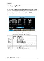
1.5V. Choose TrigLev and use the numeric keyboard to input the desired value
and select the unit (V or mV) from the pop-up menu. Or use the knob and
arrow keys to change the parameter value.
4. Coupling Mode
Sets
the coupling model of the input signal to “AC” or “DC”. The default is
“AC”.
5. HFR
High Frequency Rejection can be used to filter out the high-frequency
components of a measured signal and improve the measurement accuracy in
low-frequency signal measurement. Press HFR to enable or disable this
function. The default is “Off”.
Enable High Frequency Rejection when low-frequency signal with lower
than a 250 kHz frequency is measured to filter out the high-frequency
noise interference.
Disable High Frequency Rejection when a signal with a frequency higher
than 250 KHz is measured. The maximum frequency that can be counted
is 400 MHz.
Summary of Contents for SDG6000X Series
Page 2: ......
Page 45: ...SDG6000X User Manual 35 Figure 2 16 Setting the Bandwidth...
Page 142: ...132 SDG6000X User Manual Figure 2 95 Phase Deviation Interface...
Page 160: ...150 SDG6000X User Manual Figure 3 1 Generate a Sine Waveform...
Page 162: ...152 SDG6000X User Manual Figure 3 2 Generate a Square Waveform...
Page 175: ...SDG6000X User Manual 165 Figure 3 9 Generate an AM Modulation Waveform...
Page 177: ...SDG6000X User Manual 167 Figure 3 10 Generate a FM Modulation Waveform...
Page 179: ...SDG6000X User Manual 169 Figure 3 11 Generate a PM Modulation Waveform...
Page 181: ...SDG6000X User Manual 171 Figure 3 12 Generate a FSK Modulation Waveform...
Page 183: ...SDG6000X User Manual 173 Figure 3 13 Generate an ASK Modulation Waveform...
Page 185: ...SDG6000X User Manual 175 Figure 3 14 Generate a PSK Modulation Waveform...
Page 187: ...SDG6000X User Manual 177 Figure 3 15 Generate a PWM Modulation Waveform...
Page 189: ...SDG6000X User Manual 179 Figure 3 16 Generate a DSB AM Modulation Waveform...

