SDG6000X User Manual 125
2.8.4 Output
Press Utility
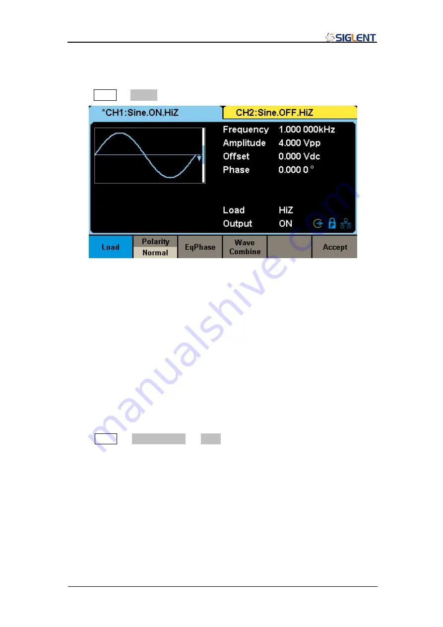
→ Output to enter the following interface.
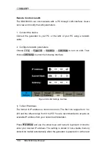
Figure 2-90 Output Setup Interface
Load
For the [CH1] and [CH2] connectors on the front panel, the generator always
has
an output impedance of 50Ω, but the instrument features a load setting
that is used to adjust the displayed amplitude setpoint based on the expected
external load impedance. If the actual load does not match the set load, the
displayed voltage will not be the same as the output voltage. This function is
used to match the displayed voltage with the expected one. This setting does
not actually change the output impedance to any other value.
Press Utility
→ Output Setup → Load, to select “HighZ” or “50Ω”, or use the
numeric keyboard to set a specific impedance value. The available range is
from 50
Ω to 100 kΩ. The default is “HighZ”.
Pressing the corresponding output key for two seconds will switch
between High Impedance and 50Ω
The generator will adjust the output amplitude and offset voltage
automatically once the load setting is changed. For example, if the
amplitude is set to
“5 Vpp” with the load impedance set to “50 Ω”, it will
Summary of Contents for SDG6000X Series
Page 2: ......
Page 45: ...SDG6000X User Manual 35 Figure 2 16 Setting the Bandwidth...
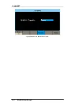
Page 142: ...132 SDG6000X User Manual Figure 2 95 Phase Deviation Interface...
Page 160: ...150 SDG6000X User Manual Figure 3 1 Generate a Sine Waveform...
Page 162: ...152 SDG6000X User Manual Figure 3 2 Generate a Square Waveform...
Page 175: ...SDG6000X User Manual 165 Figure 3 9 Generate an AM Modulation Waveform...
Page 177: ...SDG6000X User Manual 167 Figure 3 10 Generate a FM Modulation Waveform...
Page 179: ...SDG6000X User Manual 169 Figure 3 11 Generate a PM Modulation Waveform...
Page 181: ...SDG6000X User Manual 171 Figure 3 12 Generate a FSK Modulation Waveform...
Page 183: ...SDG6000X User Manual 173 Figure 3 13 Generate an ASK Modulation Waveform...
Page 185: ...SDG6000X User Manual 175 Figure 3 14 Generate a PSK Modulation Waveform...
Page 187: ...SDG6000X User Manual 177 Figure 3 15 Generate a PWM Modulation Waveform...
Page 189: ...SDG6000X User Manual 179 Figure 3 16 Generate a DSB AM Modulation Waveform...

