SDG6000X User Manual 51
Table 2-9 Correspondence between logic level and high, low level
Logic Level
High Level
Low Level
TTL/CMOS
5 V
0 V
LVTTL/LVCOMS 3.3 V
0 V
ECL
-900 mV
-1.7 V
LVPECL
2.4 V
1.6 V
LVDS
1.6 V
900 mV
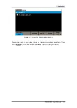
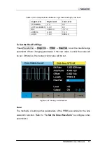
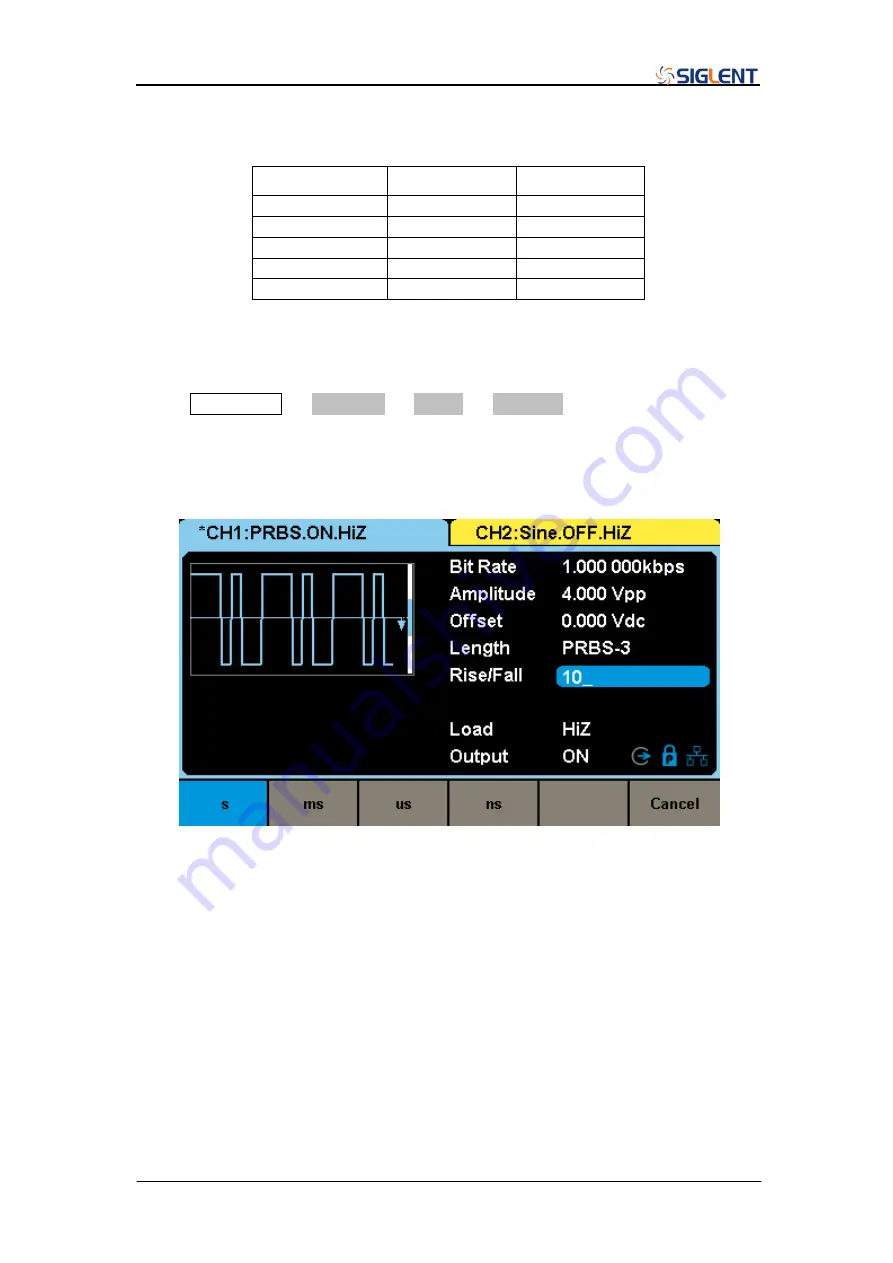
To Set the Rise/Fall Edge
Press Waveforms
→ Page 1/2 → PRBS → Rise/Fall, to set the rise/fall edge
parameter. When changing parameter, if the new value is valid, the value will
be set. Otherwise, the nearest valid value will be set.
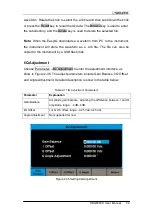
Figure 2-27 Setting the Rise/Fall
Note:
The methods of setting other parameters of the PRBS are similar to the sine
waveform function.
Refer to “
” to configure other
parameters.
Summary of Contents for SDG6000X Series
Page 2: ......
Page 45: ...SDG6000X User Manual 35 Figure 2 16 Setting the Bandwidth...
Page 142: ...132 SDG6000X User Manual Figure 2 95 Phase Deviation Interface...
Page 160: ...150 SDG6000X User Manual Figure 3 1 Generate a Sine Waveform...
Page 162: ...152 SDG6000X User Manual Figure 3 2 Generate a Square Waveform...
Page 175: ...SDG6000X User Manual 165 Figure 3 9 Generate an AM Modulation Waveform...
Page 177: ...SDG6000X User Manual 167 Figure 3 10 Generate a FM Modulation Waveform...
Page 179: ...SDG6000X User Manual 169 Figure 3 11 Generate a PM Modulation Waveform...
Page 181: ...SDG6000X User Manual 171 Figure 3 12 Generate a FSK Modulation Waveform...
Page 183: ...SDG6000X User Manual 173 Figure 3 13 Generate an ASK Modulation Waveform...
Page 185: ...SDG6000X User Manual 175 Figure 3 14 Generate a PSK Modulation Waveform...
Page 187: ...SDG6000X User Manual 177 Figure 3 15 Generate a PWM Modulation Waveform...
Page 189: ...SDG6000X User Manual 179 Figure 3 16 Generate a DSB AM Modulation Waveform...

