84 SDG6000X User Manual
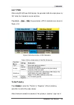
the modulating waveform amplitude corresponds to carrier phase output and
log
ic high corresponds to modulating phase output; if the polarity is “negative”,
the situation is the opposite.
When external modulation is selected, if the polarity is “positive”, logic low of
the input corresponds to carrier phase output and logic high corresponds to
modulating phase output; if the polarity is “negative”, the situation is the
opposite.
Note:
The way of setting the parameters of PSK is similar to FSK. In addition, the
external modulating signal of PSK must comply with the 5V CMOS level
specification.
Summary of Contents for SDG6000X Series
Page 2: ......
Page 45: ...SDG6000X User Manual 35 Figure 2 16 Setting the Bandwidth...
Page 142: ...132 SDG6000X User Manual Figure 2 95 Phase Deviation Interface...
Page 160: ...150 SDG6000X User Manual Figure 3 1 Generate a Sine Waveform...
Page 162: ...152 SDG6000X User Manual Figure 3 2 Generate a Square Waveform...
Page 175: ...SDG6000X User Manual 165 Figure 3 9 Generate an AM Modulation Waveform...
Page 177: ...SDG6000X User Manual 167 Figure 3 10 Generate a FM Modulation Waveform...
Page 179: ...SDG6000X User Manual 169 Figure 3 11 Generate a PM Modulation Waveform...
Page 181: ...SDG6000X User Manual 171 Figure 3 12 Generate a FSK Modulation Waveform...
Page 183: ...SDG6000X User Manual 173 Figure 3 13 Generate an ASK Modulation Waveform...
Page 185: ...SDG6000X User Manual 175 Figure 3 14 Generate a PSK Modulation Waveform...
Page 187: ...SDG6000X User Manual 177 Figure 3 15 Generate a PWM Modulation Waveform...
Page 189: ...SDG6000X User Manual 179 Figure 3 16 Generate a DSB AM Modulation Waveform...

