background image


SDG6000X  User  Manual        85 

2.4.8  PWM 


In PWM (Pulse Width Modulation), the pulse width of the pulse varies with the 

instantaneous  voltage  of  the  modulating  waveform.  The  carrier  can  only  be 

pulse. 


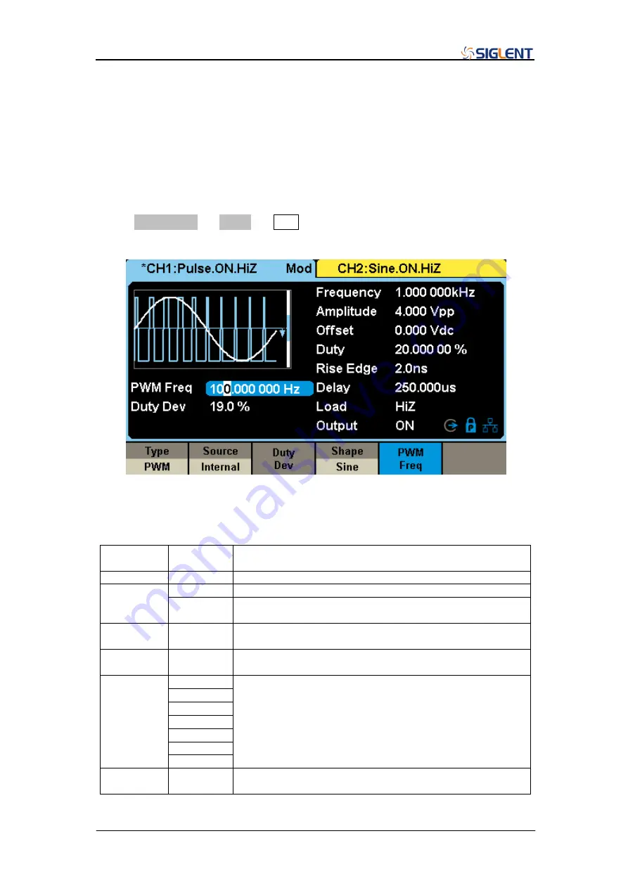
Press Waveforms 

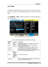
→ Pulse →  Mod, the parameters of PWM modulation are 

shown in Figure 2-55


Figure 2-55 Setting Interface of PWM Modulation 


Table 2-19 Menu Explanations of the PWM Parameters 

Function 
Menu 

Settings 

Explanation 

Type 

PWM 

Pulse width modulation. The available carrier is pulse 

Source 

Internal 

The source is internal 

External 

The source is external signal from the [Aux In/Out] 
connector at the rear panel 

Width Dev 


The deviation from the carrier pulse width (only when 
pulse width is the current parameter of the carrier) 

Duty Dev 


The deviation from the carrier duty cycle (only when duty 
cycle is the current parameter of the carrier) 

Shape 

Sine 

The modulating waveform 

Square 
Triangle 
UpRamp 
DnRamp 
Noise 
Arb 

PWM Freq 


Set the modulating waveform frequency. Frequency range: 
1mHz~1MHz (internal source only) 


Summary of Contents for SDG6000X Series

Page 1: ...User Manual SDG6000X Series Pulse Arbitrary Waveform Generator UM0206X E01A 2017 SIGLENT TECHNOLOGIES CO LTD...

Page 2: ......

Page 3: ...SDG6000X User Manual I Declaration Copyright SIGLENT TECHNOLOGIES CO LTD All rights reserved Without permission contents in this manual are not allowed to be copied extracted or translated...

Page 4: ...strument is grounded correctly before connecting its input or output terminals Connect the signal wire correctly The potential of the signal wire ground is equal to the earth therefore do not connect...

Page 5: ...mmediately happen WARNING Indicates an injury or hazard that may not immediately happen CAUTION Indicates that a potential damage to the instrument or other property might occur Symbols used on the in...

Page 6: ...mple rate of 2 4 GSa s and 16 bit vertical resolution They also include proprietary TrueArb EasyPulse technology that help to solve the weaknesses inherent in traditional DDS generators when generatin...

Page 7: ...s the full frequency range Function Arbitrary Waveform Generator Basic Function Arbitrary Waveform Generator with modulation sweep burst and waveform combination functions IQ Signal Generator optional...

Page 8: ...ommon Function Keys 19 2 Application and Implementation 20 2 1 To Set the Standard Waveforms 21 2 1 1 To Set the Sine Waveform 21 2 1 2 To Set the Square Waveform 25 2 1 3 To Set the Ramp Waveform 27...

Page 9: ...6 Remote Interface 133 2 8 7 Sync Output 139 2 8 8 Clock Source 141 2 8 9 Phase Mode 143 2 8 10 Overvoltage Protection 145 2 8 11 Multi Device Synchronization 146 3 Examples 148 3 1 Example 1 Generati...

Page 10: ...14 Generating a PSK Modulation Waveform 174 3 15 Example 15 Generating a PWM Modulation Waveform 176 3 16 Example 16 Generating a DSB AM Modulation Waveform 178 3 17 Example 17 Generating a IQ Wavefor...

Page 11: ...SDG6000X User Manual 1 1 Quick Start This chapter covers the following topics Handle Adjustment The Front Rear Panel Touch Screen Display System Functions...

Page 12: ...r Manual 1 1 Handle Adjustment To adjust the handle position of SDG6000X please grip the handle by the sides and pull it outward Then rotate to the desired position Figure 1 1 Viewing Position and Car...

Page 13: ...the front rear panel 1 2 1 Front Panel SDG6000X has a clear and simple front panel which includes 4 3 inch touch screen menu softkeys numeric keyboard knob function keys arrow keys and channel control...

Page 14: ...Interface USB Device 1 2 2 Rear Panel The rear panel provides multiple interfaces including Counter 10 MHz In 10 MHz Out Aux In Out LAN USB Device Earth Terminal and AC Power Supply Input Figure 1 3 R...

Page 15: ...en You can use your finger or a touch pen to control the instrument Most functions and selections can be chosen using the touch screen in a similar manner to the front panel keys and knob Figure 1 4 T...

Page 16: ...to highlight it and then use the softkeys number keys or knob to change the parameter value or press the corresponding output key for two seconds to switch between High Impedance and 50 High Impedanc...

Page 17: ...essages based on the current clock source This mark indicates the current clock source is from the internal TCXO This mark indicates the current clock source is from an external clock source 8 Menu Sh...

Page 18: ...menu as Figure 1 5 shows The example below will help to familiarize with the waveform selection settings Figure 1 5 Waveform Selections Press Waveforms Sine and the channel status bar displays Sine T...

Page 19: ...Cycle a square waveform with different parameters can be generated Figure 1 7 Square Display Interface Press Waveforms Ramp and channel status bar displays Ramp The generator can generate ramp wavefo...

Page 20: ...and rise fall times By setting Frequency Period Amplitude High level Offset Low level PulWidth Duty Rise Fall and Delay a pulse waveform with different parameters can be generated Figure 1 9 Pulse Di...

Page 21: ...level up to 10 V into a HighZ load or 5 V into a 50 load Figure 1 11 DC Display Interface Press Waveforms Page 1 2 Arb and channel status bar displays Arb The generator can generate repeatable arbitr...

Page 22: ...ress Waveforms Page 1 2 I Q then CH1 and CH2 output orthogonal I and Q signals respectively and channel status bar displays In phase and Quadrature separately The generator can generate I Q signals wi...

Page 23: ...The generator can generate a Pseudo Random Bit Sequence PRBS with bit rates ranging from 1 bps to 300 Mbps By setting BitRate Period Amplitude High level Offset Low level Length Logic Level and Rise...

Page 24: ...arameters such as Type Source AM Depth AM Freq and Shape The SDG6000X can modulate waveforms using AM FM PM ASK FSK PSK PWM and DSB AM modulation types Pulse waveforms can only be modulated using PWM...

Page 25: ...nterface 3 Press Burst the Burst function will be enabled Burst function is supported for Sine Square Ramp Pulse or Arbitrary waveforms Start Phase ranges from 0 to 360 and the Burst Period ranges fro...

Page 26: ...t of the two channels Choose a channel and press the corresponding Output key the key backlight will light and the output will be enabled Press the Output key again the key light will go out and the o...

Page 27: ...g parameters 3 When using the knob to set parameters the arrow keys are used to select the digit placeholder to be modified When using the numeric keyboard to set parameters the left arrow key is used...

Page 28: ...Manual Figure 1 21 Use numeric keyboard to set the parameters When using the numeric keyboard to enter the value the left arrow key can be used to move the cursor backward and delete the value of the...

Page 29: ...ters frequency amplitude etc of basic waveforms 2 The Utility key is used to set the auxiliary system functions such as output configurations interface setting system setting information performing th...

Page 30: ...know how to set your Pulse Arbitrary Waveform Generator for your usage If you are not familiar with these operations you are suggested to read chapter one Quick Start again This chapter covers the fo...

Page 31: ...e operation menu as shown in Figure 2 1 The parameters available for sine waveform include frequency period amplitude high level offset low level and phase Different sine signals can be generated by s...

Page 32: ...1 kHz Press Waveforms Sine Frequency to set the frequency parameter When changing parameters if the new value is valid the value will be set If the new value is invalid the instrument will set the val...

Page 33: ...etting the Amplitude Note If the output load is set to a specific resistance value not HiZ the amplitude unit can be set as Vpp mVpp Vrms mVrms or dBm If load is set as HighZ the amplitude unit can be...

Page 34: ...in to switch to low level entry Figure 2 4 Setting the Offset To Set the Phase Press Waveforms Sine Phase to set the phase parameter When changing parameter if the new value is valid the value will be...

Page 35: ...splay Interface Table 2 2 Menu Explanations of Square Waveform Note To select the secondary menu item press the key a second time For example if you wish to adjust the period of a waveform press the s...

Page 36: ...00X Datasheet The default value is 50 Press Waveforms Square DutyCycle to set the duty cycle parameter When changing parameter if the new value is valid the value will be set Otherwise the nearest val...

Page 37: ...ay Interface Table 2 3 Menu Explanations of Ramp Waveform Note To select the secondary menu item press the key a second time For example if you wish to adjust the period of a waveform press the softke...

Page 38: ...rms Ramp Symmetry to set the symmetry parameter When changing parameter if the new value is valid the value will be set Otherwise the nearest valid value will be set Figure 2 9 Setting the Symmetry No...

Page 39: ...enu Explanations of Pulse Waveform Note To select the secondary menu item press the key a second time For example if you wish to adjust the period of a waveform press the softkey Function Menu Explana...

Page 40: ...For detailed information please refer to SDG6000X Datasheet The default value is 200 s Pulse duty cycle is defined as the percentage that the pulse width takes up in the whole period Pulse duty cycle...

Page 41: ...n from 90 to 10 threshold The setting of rise fall edge time is limited by the currently specified pulse width limit Users can set rise edge and fall edge independently Press Waveforms Pulse Rise to s...

Page 42: ...X User Manual Figure 2 12 Setting the Rise Edge Note The methods of setting other parameters of pulse signal are similar to sine waveform function Refer to To Set the Sine Waveform to configure other...

Page 43: ...signal which has no frequency or period Figure 2 13 Noise Parameters Display Interface Table 2 5 Menu Explanations of Noise To Set the Stdev Press Waveforms Noise Stdev to set the stdev parameter Whe...

Page 44: ...ter if the new value is valid the value will be set Otherwise the nearest valid value will be set Figure 2 15 Setting the Mean Bandwidth Press Waveforms Noise BandSet and choose On and then the bandwi...

Page 45: ...SDG6000X User Manual 35 Figure 2 16 Setting the Bandwidth...

Page 46: ...r the following interface Please note that there is a DC offset parameter at the middle of the screen Figure 2 17 DC Setting Interface Note The method of setting offset of a DC signal is similar to Of...

Page 47: ...re stored in the internal non volatile memory TrueArb output mode allows creation of arbitrary waveforms that contain from 2 to 20 Mpts TrueArb Choose Waveforms Page 1 2 Arb Arb Mode and select the Tr...

Page 48: ...ey a second time For example if you wish to adjust the period of a waveform press the softkey below the Frequency Period menu label until Period is highlighted and then enter the value To Set the Samp...

Page 49: ...wave with 0 order hold interpolation and linear interpolation Figure 2 19 Comparison of 0 order hold and Linear Interpolation Modes DDS Choose Waveforms Page 1 2 Arb Arb Mode and select the DDS outpu...

Page 50: ...form to configure other parameters Built in Arbitrary Waveform There are plenty of built in Arbitrary Waveforms as well as user defined Arbitrary Waveforms stored in the generator To select one of the...

Page 51: ...Ramp waveform DnRamp Down Ramp waveform SineTra Sine Tra waveform SineVer Sine Ver waveform Math ExpFall Exponential Fall function ExpRise Exponential Rise function LogFall Log Fall function LogRise...

Page 52: ...gnal Quake Analog quake waveform Chirp Chirp signal TwoTone TwoTone signal SNR Sine signal with noise AmpALT Increasing oscillation curve AttALT Descreasing oscillation curve RoundHalf RoundHalf Wavef...

Page 53: ...w Blackman Blackman window GaussiWin Gaussian window Triangle Triangle window Fejer window BlackmanH BlackmanH window Bartlett Hann Bartlett Hann window Bartlett Bartlett window BohmanWin Bohman windo...

Page 54: ...cycle SquareDuty12 Square waveform with 12 duty cycle SquareDuty14 Square waveform with 14 duty cycle SquareDuty16 Square waveform with 16 duty cycle SquareDuty18 Square waveform with 18 duty cycle Sq...

Page 55: ...SquareDuty72 Square waveform with 72 duty cycle SquareDuty74 Square waveform with 74 duty cycle SquareDuty76 Square waveform with 76 duty cycle SquareDuty78 Square waveform with 78 duty cycle SquareD...

Page 56: ...rve stimulation electrotherapy Tens2 Waveform 2 of the nerve stimulation electrotherapy Tens3 Waveform 3 of the nerve stimulation electrotherapy Mod AM Sectional sine AM signal FM Sectional sine FM si...

Page 57: ...00X User Manual 47 Figure 2 22 Stored Waveform Display Interface Rotate the knob or touch the screen to choose the desired waveform Then select Recall or press the knob to recall the corresponding wav...

Page 58: ...evel length logic level and rise fall Figure 2 23 PRBS setting interface Table 2 8 Menu Explanations of PRBS Note To select the secondary menu item press the key a second time For example if you wish...

Page 59: ...is valid the value will be set Otherwise the nearest valid value will be set If Period rather than BitRate is the desired parameter press BitRate Period again to enter the period mode Figure 2 24 Set...

Page 60: ...the logic level By selecting the corresponding type of logic level the high level and low level of PRBS can be configured automatically If Differential is set to ON channel one will output the wavefo...

Page 61: ...o Set the Rise Fall Edge Press Waveforms Page 1 2 PRBS Rise Fall to set the rise fall edge parameter When changing parameter if the new value is valid the value will be set Otherwise the nearest valid...

Page 62: ...fundamental waveform where A1 is the fundamental waveform amplitude and 1 is the fundamental waveform phase The frequencies of the other components harmonics are all integral multiples of the fundamen...

Page 63: ...l waveform and its odd harmonics 3 Press All the instrument will output fundamental waveform and all the user defined orders of harmonics To Set the Harmonic Order After entering the harmonic setting...

Page 64: ...onic Phase After entering the harmonic setting menu press Harmonic Phase to set the phase of selected harmonic 1 Press Order to select the sequence number of the harmonic to be set 2 Press Harmonic Ph...

Page 65: ...32X Resampling 32X Digital Quadrature Modulator D A D A I Data RAM Q Data RAM 500Sa s 75MSa s 75MSa s 2 4GSa s Iout Qout IQ Data Flow Figure 2 29 IQ modulation 2 3 1 Front Panel IQ Control Press Wave...

Page 66: ...enter frequency is the intermediate frequency The figure below shows the diagram of the IQ modulator in the SDG6000X Figure 2 31 Iin t cosine sine Qin t CH1 CH2 Figure 2 31 IQ Modulator in the SDG6000...

Page 67: ...set the amplitude When the unit is Vrms mVrms or dBm the amplitude equal to the modulus of the I Q 2 2 I Q Figure 2 33 Setting the Amplitude To Set the Trigger Source Press Parameter Trigger Source to...

Page 68: ...ux In Out input 5V CMOS pulse with the specified polarity 3 Manual Trigger Choose Trigger Source Manual and one period of the IQ waveform will be generated once the Trigger softkey is pressed I Q Data...

Page 69: ...file can also be copied to the instrument by a USB flash disk I Q Adjustment Choose Parameter I Q Adjustment to enter the adjustment interface as show in Figure 2 35 The adjust parameters include Gain...

Page 70: ...includes Data Source Modulation and Filter as show in Figure 2 36 Figure 2 36 EasyIQ Interface 2 3 2 1 Data Source Data Source panel sets parameters for the symbol data that is to be modulated As show...

Page 71: ...r its period User File When selecting User File as data source type a file selection dialog box pops up for you to select a TXT txt file as input data bits In the user data file only 0 or1 is acceptab...

Page 72: ...Symbol Displays the number of bits contained in one modulated symbol It is read only not settable 2 3 2 2 Modulation Modulation panel sets parameters for user selected modulation type Figure 2 39 Modu...

Page 73: ...to show a zoomed window of the constellation you can also double click on the zoomed constellation window to close it Gray Turns ON or OFF the Gray code for the constellation data Default OFF MFSK Sel...

Page 74: ...ly be selected as Gaussian Multitone Check the to set the multi tone signal Below is the interpretion for the multi tone parameters Sample Rate sample rate of multi tone modulation in MHz Range 0 002...

Page 75: ...r delete constellation points and edit the IQ data for each constellation point manually You can also recall constellation data from an existing file and save the edited constellation data to a new fi...

Page 76: ...ters including raised cosine filter root raised cosine filter and Gaussian filter To interface is shown in Figure 2 42 Figure 2 42 Filter interface Filter Type Sets filter type for current modulation...

Page 77: ...yed on the lower half of the main window You can click FFT Spectrum or IQ Waveform tab to display the Frequency domain waveform or Time domain waveform alternatively Notes 1 Right click on the wavefor...

Page 78: ...he Time domain plot of modulated IQ data is displayed Figure 2 44 Time domain Waveform The I Q data plots are displayed separately in two graphs The horizontal coordinate shows the symbol values and t...

Page 79: ...ccess the SDG6000X USB Device If the SDG6000X is connected to the PC through USB device correctly in the VISA Address drop down list the USBTMC Visa address of the SDG6000X will be displayed as shown...

Page 80: ...G6000X User Manual address of the SDG6000X to replace the LOCALHOST characters as shown in Figure 2 47 And then click the download button to download the waveform data Figure 2 47 Download Data throug...

Page 81: ...and carrier In FM users can set the source internal external modulating frequency frequency deviation modulating waveform and carrier In PM users can set the source internal external phase deviation m...

Page 82: ...gure 2 48 Figure 2 48 Setting Interface of AM Modulation Table 2 12 Menu Explanations of the AM Parameters Function Menu Settings Explanation Type AM Amplitude modulation Source Internal The source is...

Page 83: ...elected the generator accepts external modulating signals from the Aux In Out connector at the rear panel At this time the amplitude of the modulated waveform is controlled by the signal level applied...

Page 84: ...umeric keyboard or arrow keys and knob to input the desired value The amplitude of AM modulated waveform varies with different modulation depth but the power of the carrier is constant For an external...

Page 85: ...u Explanations of the DSB AM Parameters Function Menu Settings Explanation Type DSB AM DSB Amplitude modulation Source Internal The source is internal External The source is external signal from the A...

Page 86: ...re 2 50 Setting Interface of FM Modulation Table 2 14 Menu Explanations of the FM Parameters Function Menu Settings Explanation Type FM Frequency modulation Source Internal The source is internal Exte...

Page 87: ...odulated waveform is controlled by the signal level applied to the connector For example if the frequency deviation is set to 1 kHz the output frequency will increase 1 kHz based on the carrier freque...

Page 88: ...2 51 Figure 2 51 Setting Interface of PM Modulation Table 2 15 Menu Explanations of the PM Parameters Function Menu Settings Explanation Type PM Phase modulation Source Internal The source is interna...

Page 89: ...r at the rear panel At this time the phase of the modulated waveform is controlled by the signal level applied to the connector For example if the phase deviation is set to 180 the output phase will i...

Page 90: ...Explanations of the FSK Parameters Function Menu Settings Explanation Type FSK Frequency shift keying modulation Source Internal The source is internal External The source is external signal from the...

Page 91: ...hen internal modulation source is selected press Key Freq to set the rate at which the output frequency shifts between carrier frequency and hop frequency Use the numeric keyboard or arrow keys and kn...

Page 92: ...SK Modulation Table 2 17 Menu Explanations of the ASK Parameters Function Menu Settings Explanation Type ASK Amplitude shift keying modulation Source Internal The source is internal External The sourc...

Page 93: ...ion Type PSK Phase shift keying modulation Source Internal The source is internal External The source is external signal from the Aux In Out connector at the rear panel PSK Rate Frequency at which the...

Page 94: ...ite When external modulation is selected if the polarity is positive logic low of the input corresponds to carrier phase output and logic high corresponds to modulating phase output if the polarity is...

Page 95: ...xplanation Type PWM Pulse width modulation The available carrier is pulse Source Internal The source is internal External The source is external signal from the Aux In Out connector at the rear panel...

Page 96: ...Dev to highlight the parameter and use the numeric keyboard or arrow keys and knob to input the desired value Width Deviation represents the maximum variation of the modulated waveform pulse width rel...

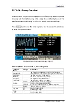
Page 97: ...20 Menu Explanations of Sweep Page 1 2 Function Menu Settings Explanation Sweep time The time span of the sweep in which the frequency changes between the start frequency to stop frequency Start Freq...

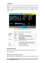
Page 98: ...start freq stop freq or center freq freq span to set the range of the frequency sweep Start Frequency and Stop Frequency Start Frequency and Stop Frequency are the lower and upper limits of the Functi...

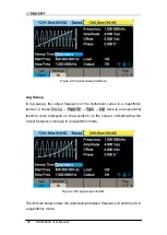
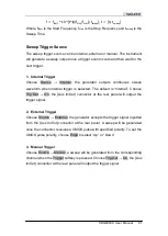
Page 99: ...n from Stop frequency to Start frequency Center Frequency and Frequency Span Center Frequency Start Frequency Stop Frequency 2 Frequency Span Stop Frequency Start Frequency Sweep Type SDG6000X provide...

Page 100: ...in a logarithmic fashion Choose Sweep Page 1 2 Type Log there is an exponential function curve displayed on the waveform on the screen indicating that the output frequency changes in a logarithmic mod...

Page 101: ...trigger is selected The default is Internal Choose Trig Out On the Aux In Out connector at the rear panel will output the trigger signal 2 External Trigger Choose Source External the generator accept...

Page 102: ...ong burst type trigger source and carrier Burst Type Trigger Source Carrier N Cycle Internal External Manual Sine Square Ramp Pulse Arbitrary Gated Internal External Sine Square Ramp Pulse Noise Arbit...

Page 103: ...cle Infinite Set the number of the bursts in N Cycle to be infinite Start Phase The start phase of the carrier Burst Period The burst period Only valid when Source is Internal Source Internal Choose i...

Page 104: ...cording to the gate signal level When the gated signal is true the generator outputs a continuous waveform When the gated signal is false the generator first completes the output of the current period...

Page 105: ...f the waveform For Pulse and Noise the Start Phase is unavailable Burst Period The time from the beginning of a burst to the beginning of the next burst It is only available in internal trigger mode W...

Page 106: ...urst waveform when internal trigger is selected Choose Trig Out as Up Down the Aux In Out connector at the rear panel will output a trigger signal with specified edge or choose Trig Out as Off the tri...

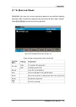
Page 107: ...ollowing interface Figure 2 63 Store Recall Interface Page 1 2 Table 2 26 Menu Explanations of Save and Recall Function Menu Settings Explanation File Type State The setting of the generator Data Arbi...

Page 108: ...states and arbitrary waveform files to C Disk 2 USB Device 0 There is a USB Host interface located on the left side of the front panel which permits users to store recall waveforms or update the firm...

Page 109: ...nd underscore If other characters are used the name may be displayed in the store and recall interface abnormally Browse Use the knob to shift between the directories or click the corresponding locati...

Page 110: ...t parameters of two channels and utility parameters Data File The SDG6000X can recall the data files in csv or dat format from an external memory device transform them into bin format then store them...

Page 111: ...parameters and other utility settings used To save the instrument state the procedures are given as followed 1 Choose the file type to store Press Store Recall File Type State to choose state as the s...

Page 112: ...input the character selected in the filename area A quick alternative is to touch the location of the character on the screen directly Delete the character Use the left and right arrow keys to move th...

Page 113: ...Rotate the knob or click the touch screen to select the file you want to delete 2 Delete the file Choose Delete then the generator will display prompt message Delete the file Pressing Accept will dele...

Page 114: ...104 SDG6000X User Manual Page 1 2 Copy 3 Paste the file Rotate the knob to select Local C and press the knob to open its directory Then press Paste...

Page 115: ...n Figure 2 67 Figure 2 68 and Figure 2 69 Figure 2 67 Utility Setup Interface Page 1 3 Table 2 29 Menu Explanations of Utility Page1 3 Function Menu Settings Explanation System The system configuratio...

Page 116: ...ion Menu Settings Explanation Interface Remote interfaces setting Sync Sync output setting Clock System clock source setting Phase Mode Phase Locked Phase mode Independent OverVoltage Protection On Tu...

Page 117: ...SDG6000X User Manual 107 Table 2 31 Menu Explanations of Utility Page 3 3 Function Menu Settings Explanation Multi Device Sync Multi Device Synchronization setting Page 3 3 Return to the page 1...

Page 118: ...s Explanation Number format The number format Language English System language Chinese Power On Setting Default All the settings return to default when power on Last All the settings return to the set...

Page 119: ...d set the elapsed inactive time that must pass before activating the screen 1min 5min 15min 30min 1hour 2hour 5hour System Info View the system information Firmware Update Update the firmware by the U...

Page 120: ...eparator Space Use Space as the separator Done Save the current settings and return to the System menu According to the different choices of the decimal point and the separator the format can have var...

Page 121: ...setting when the generator is powered on Three choices are available Default Last and User Once selected the setting will be applied when the instrument is powered on This setting is stored in non vol...

Page 122: ...le in the interface and recall an instrument state file in xml format Figure 2 75 User Power on Setting Interface 2 8 1 4 Set to Default Press Utility System Set To Default to set the system to the de...

Page 123: ...ear Direction Burst Default Burst Period 10 ms Start Phase 0 Cycles 1 cycle Trig Out Off Delay 521 ns Trigger Default Source Internal 2 8 1 5 Beeper Enable or disable the beeper Press Utility System B...

Page 124: ...e The software version and configuration file of the generator can be updated directly via U disk Follow the steps below 1 Insert U disk with firmware update file ADS and configuration file CFG to USB...

Page 125: ...System The SDG6000X provides a built in help system for basic assistance with button functions Press Utility System Page 1 2 Help to enter the following interface Figure 2 77 Help Menu Table 2 36 Hel...

Page 126: ...interface Press Utility System Page 1 2 UI Style to select the desired interface style This setting is stored in non volatile memory and will not be influenced by the Set To Default operation Normal...

Page 127: ...Test Cal function Menu Table 2 37 Menu Explanations of Test Cal Setting Function Menu Explanation SelfTest Perform a system self test TouchCal Do a touch screen calibration Return Return to the Utilit...

Page 128: ...continue press 8 key to exit is displayed Press the 7 key for test and observe if there is any serious color deviation bad pixels or other display error Figure 2 82 Screen Test Interface 2 Key Test S...

Page 129: ...8 key three times to exit 3 LED Test Select LEDTest to enter the LED test interface the on screen white rectangle shapes represent the front panel keys The prompt message Please press 7 Key to continu...

Page 130: ...85 Board Test Interface Touch Adjust Use the function regularly to calibrate the touch screen which makes it more accurate when a finger or touch pen touches the screen and avoids any misoperation Pre...

Page 131: ...upper left corner upper right corner lower left corner and lower right corner of the screen in sequence After touch calibration is done the system will display the following tip Then press any key or...

Page 132: ...2 39 Menu Explanations of Frequency Counter Function Menu Settings Explanation State Off Open the counter On Close the counter Frequency Measured frequency Period Measured period PWidth Measured posit...

Page 133: ...and return to the previous menu 1 To Select the Parameters to be measured The frequency counter on the SDG6000X can measure parameters including frequency period duty positive pulse width and negative...

Page 134: ...ction can be used to filter out the high frequency components of a measured signal and improve the measurement accuracy in low frequency signal measurement Press HFR to enable or disable this function...

Page 135: ...the same as the output voltage This function is used to match the displayed voltage with the expected one This setting does not actually change the output impedance to any other value Press Utility O...

Page 136: ...o the offset voltage as shown in the following figure Note The Sync signal related to the waveform is not inverted when the waveform is inverted EqPhase Press Utility Output Setup EqPhase to align the...

Page 137: ...ion Menu Settings Explanation CH1 Switch CH1 Output the waveform of CH1 CH1 CH2 Output the waveform of CH1 CH2 CH2 Switch CH2 Output the waveform of CH2 CH1 CH2 Output the waveform of CH1 CH2 Return S...

Page 138: ...owing interface Figure 2 92 Channel Copy Interface Table 2 42 Menu Explanations of Channel Copy Function Menu Settings Explanation CH1 CH2 Copy all parameters and states of CH1 to CH2 CH2 CH1 Copy all...

Page 139: ...automatically and always keeps the specified frequency deviation ratio amplitude deviation ratio or phase deviation ratio relative to the base channel Press Utility CH Copy Coupling Channel Coupling t...

Page 140: ...upling 1 To Enable Phase Coupling Function Press PhaseCoup to turn phase coupling On or Off The default is Off 2 To Select Phase Coupling Mode Press PhaseMode to choose Deviation or Ratio and then use...

Page 141: ...al channels can output the same signal Choose Utility CH Copy Coupling Track to enable or disable the track function When the track function is enabled channel copy and coupling functions are disabled...

Page 142: ...132 SDG6000X User Manual Figure 2 95 Phase Deviation Interface...

Page 143: ...pen the following menu The user can set LAN parameters or GPIB address Figure 2 96 Interface Settings Table 2 43 Menu Explanations of Interface Function Menu Settings Explanation GPIB Set the GPIB add...

Page 144: ...vice Connect the USB Device interface at the rear panel of SDG6000X with the PC via a USB cable 2 Install the USB driver The latest National Instruments Visa Runtime is recommended 3 Communicate with...

Page 145: ...been connected to your PC 3 Set the GPIB address Choose Utility Page 1 2 Interface GPIB to enter the following interface Users can use the knob arrow keys or numeric keyboard to change the value and...

Page 146: ...AN Then choose LAN Setup to enter the following interface Figure 2 98 LAN Settings Interface 1 To Set IP Address The format of IP address is nnn nnn nnn nnn The first nnn ranges from 1 to 223 and the...

Page 147: ...ress Gateway and use the arrow keys and numeric keyboard or knob to enter your desired gateway The setting is stored in non volatile memory and will be loaded automatically when the generator is power...

Page 148: ...te with PC remotely Open Measurement Automation Explorer of NI After adding the LAN device VISA TCP IP Resource successfully choose the corresponding device name Then click Open VISA Test Panel to tur...

Page 149: ...lation Figure 2 99 Sync Output Interface Table 2 44 Menu Explanations of Sync Output Function Menu Settings Explanation State Off Close the sync output On Open the sync output Channel CH1 Set the sync...

Page 150: ...Waveform 1 When internal modulation is selected the sync signal is a Pulse with 50 ns pulse width For AM FM PM and PWM the frequency of the sync signal is the modulating frequency For ASK FSK and PSK...

Page 151: ...ck source should be a signal with frequency equal to 10 MHz and amplitude larger than 1 4 Vpp Press Utility Page 1 3 Clock to enter the following interface Figure 2 100 Clock Source Interface Source P...

Page 152: ...de the clock source from 10 MHz Out of a Generator Internal clock into multiple channels and then connect them to the 10 MHz In connectors of other generators External clock respectively and finally s...

Page 153: ...Mode to enter the phase mode setup Interface as shown in Figure 2 101 Figure 2 101 Mode Setup Interface Phase locked Mode When changing the frequency the DDSs of both channels reset and the phase devi...

Page 154: ...anges at random This mode should be used to minimize the output disruptions when changing frequencies manually This mode will deliver the smoothes transitions between frequency values When the indepen...

Page 155: ...e effect once any of the following conditions is met The absolute value of input voltage is higher than 11V 0 5 V when the amplitude of the generator is higher than or equal to 3 2 Vpp or the DC offse...

Page 156: ...ps are as follows 1 After entering Multi Device Sync setting interface set the State to ON for all instruments 2 Set one of the generator as Master and the others as Slave 3 Connect the Aux In Out of...

Page 157: ...evices is pressed There is a certain delay between the moment when the master sends the synchronous signal and the moment when the Slave s receive it Therefore the output waveforms from different gene...

Page 158: ...Pulse Waveform Example 5 Generating a Noise Example 6 Generating a Pseudo Random Binary Sequence Example 7 Generating a Linear Sweep Waveform Example 8 Generating a Burst Waveform Example 9 Generatin...

Page 159: ...board and choose the unit MHz The frequency is set to 1 MHz Set the Amplitude 1 Press Amplitude HighLevel to choose Amplitude which will display in a blue color 2 Input 5 from the keyboard and choose...

Page 160: ...150 SDG6000X User Manual Figure 3 1 Generate a Sine Waveform...

Page 161: ...1 Press Amplitude HighLevel to choose Amplitude which will display in a blue color 2 Input 2 from the keyboard and choose the unit Vpp The amplitude is set to 2 Vpp Set the Offset 1 Press Offset LowL...

Page 162: ...152 SDG6000X User Manual Figure 3 2 Generate a Square Waveform...

Page 163: ...ay in a blue color 2 Input 100 from the keyboard and choose the unit mVpp The amplitude is set to 100 mVpp Set the Offset 1 Press Offset LowLevel to choose Offset which will display in a blue color 2...

Page 164: ...154 SDG6000X User Manual waveform generated is shown in Figure 3 3 Figure 3 3 Generate a Ramp Waveform...

Page 165: ...de HighLevel and choose the HighLevel which will display in a blue color 2 Input 5 from the keyboard and choose the unit V The high level is set to 5 V Set the LowLevel 1 Press Offset LowLevel and cho...

Page 166: ...oose the unit ns The falling edge is set to 30 ns Set the Delay 1 Press Delay to choose Delay which will display in a blue color 2 Input 20 from the keyboard and choose the unit ns The delay is set to...

Page 167: ...choose Stdev which will display in a blue color 2 Input 0 5 from the keyboard and choose the unit V The stdev is set to 0 5 V Set the Mean 1 Press Mean to choose Mean which will display in a blue colo...

Page 168: ...the HighLevel 1 Press Amplitude HighLevel and choose the HighLevel which will display in a blue color 2 Input 5 from the keyboard and choose the unit V The high level is set to 5 V Set the LowLevel 1...

Page 169: ...om the keyboard and choose the unit ns The bit rate is set to 20 ns When the bit rate high level low level length and rise fall edge are set the waveform generated is shown in Figure 3 6 Figure 3 6 Ge...

Page 170: ...ll display in a blue color Input 5 from the keyboard and choose the unit Vpp to set the amplitude to 5 Vpp 2 Press Offset LowLevel to choose Offset which will display in a blue color Input 0 from the...

Page 171: ...SDG6000X User Manual 161 When all parameters above are set the linear sweep waveform generated is shown in Figure 3 7 Figure 3 7 Generate a Linear Sweep Waveform...

Page 172: ...choose Amplitude which will display in a blue color Input 4 from the keyboard and choose the unit Vpp to set the amplitude to 4 Vpp 3 Press Offset LowLevel to choose Offset which will display in a blu...

Page 173: ...t the delay Press Page 1 2 to choose Delay and input 100 from the keyboard and choose the unit s to set the delay to 100 s When all parameters above are set the waveform generated is shown in Figure 3...

Page 174: ...d choose Amplitude which will display in a blue color Input 1 from the keyboard and choose the unit Vpp to set the amplitude to 1 Vpp 4 Press Offset LowLevel and choose Offset which will display in a...

Page 175: ...SDG6000X User Manual 165 Figure 3 9 Generate an AM Modulation Waveform...

Page 176: ...vel and choose Amplitude which will display in a blue color Input 1 from the keyboard and choose the unit Vpp to set the amplitude to 1 Vpp 4 Press Offset LowLevel and choose Offset which will display...

Page 177: ...SDG6000X User Manual 167 Figure 3 10 Generate a FM Modulation Waveform...

Page 178: ...nd choose Amplitude which will display in a blue color Input 5 from the keyboard and choose the unit Vpp to set the amplitude to 5 Vpp 4 Press Offset LowLevel and choose Offset which will display in a...

Page 179: ...SDG6000X User Manual 169 Figure 3 11 Generate a PM Modulation Waveform...

Page 180: ...HighLevel and choose Amplitude which will display in a blue color Input 5 from the keyboard and choose the unit Vpp to set the amplitude to 5 Vpp 4 Press Offset LowLevel and choose Offset which will...

Page 181: ...SDG6000X User Manual 171 Figure 3 12 Generate a FSK Modulation Waveform...

Page 182: ...requency to 5 kHz 3 Press Amplitude HighLevel and choose Amplitude which will display in a blue color Input 5 from the keyboard and choose the unit Vpp to set the amplitude to 5 Vpp 4 Press Offset Low...

Page 183: ...SDG6000X User Manual 173 Figure 3 13 Generate an ASK Modulation Waveform...

Page 184: ...3 Press Amplitude HighLevel and choose Amplitude which will display in a blue color Input 5 from the keyboard and choose the unit Vpp to set the amplitude to 5 Vpp 4 Press Offset LowLevel and choose O...

Page 185: ...SDG6000X User Manual 175 Figure 3 14 Generate a PSK Modulation Waveform...

Page 186: ...he keyboard and choose the unit Vpp to set the amplitude to 5 Vpp 4 Press Offset LowLevel and choose Offset which will display in a blue color Input 0 from the keyboard and choose the unit Vdc to set...

Page 187: ...SDG6000X User Manual 177 Figure 3 15 Generate a PWM Modulation Waveform...

Page 188: ...e frequency to 2 kHz 3 Press Amplitude HighLevel and choose Amplitude which will display in a blue color Input 4 from the keyboard and choose the unit Vpp to set the amplitude to 4 Vpp 4 Press Offset...

Page 189: ...SDG6000X User Manual 179 Figure 3 16 Generate a DSB AM Modulation Waveform...

Page 190: ...generate an IQ modulation waveform with 32QAM the center frequency is 100 MHz the length is 2048 the symbol rate is 1 MSymbol s and using the RootCosine filter EasyIQ communicates with the SDG6000X th...

Page 191: ...sole Select Current Settings as the Type and select the USBTMC Visa address of the SDG6000X And then click Download to download the IQ baseband data to the SDG6000X Figure 3 18 EasyIQ Download Interfa...

Page 192: ...182 SDG6000X User Manual 2 Set the parameters Center frequency 100 MHz Amplitude 200 mVrms Fsymb 1 Ms s The settings are shown in Figure 3 19 Figure 3 19 SDG6000X IQ Interface...

Page 193: ...anically and electrically 2 Inspect the entire instrument In case there is any mechanical damage or defect or the instrument does not operate properly or fails in the performance tests notify the SIGL...

Page 194: ...3 After the inspections above restart the generator 4 If the generator still doesn t work please contact SIGLENT 2 If there is no waveform output after setting the parameters please do as the followin...

Page 195: ...GLENT will provide repair or replace the unit as described in the complete warranty statement To arrange for service or obtain a copy of the complete warranty statement please contact your nearest SIG...

Page 196: ...ax 86 755 3359 1582 sales siglent com www siglent com ens America SIGLENT Technologies America Inc 6557 Cochran Rd Solon Ohio 44139 Tel 440 398 5800 Toll Free 877 515 5551 Fax 440 399 1211 info siglen...

Page 197: ...Series Pulse Arbitrary Waveform Generator Accessories Standard Accessories Quick start 1 Power cord 1 Calibration Certificate 1 USB cable 1 BNC Coaxial Cable 2 Optional Accessories USB GPIB adapter S...

Page 198: ...from all power sources and clean it with a mild detergent and water Make sure the instrument is completely dry before reconnecting it to a power source To clean the exterior surface perform the follo...

Reviews: